Drive Enclosure
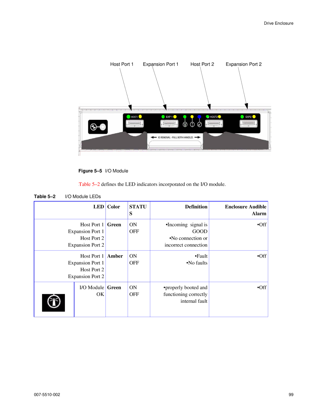
Host Port 1 | Expansion Port 1 | Host Port 2 | Expansion Port 2 |
Figure 5–5 I/O Module
ITable
Table | I/O Module LEDs |
|
|
|
| |
|
| LED | Color | STATU | Definition | Enclosure Audible |
|
|
|
| S |
| Alarm |
|
|
|
|
|
|
|
|
| Host Port 1 | Green | ON | •Incoming signal is | •Off |
| Expansion Port 1 |
| OFF | GOOD |
| |
|
| Host Port 2 |
|
| •No connection or |
|
| Expansion Port 2 |
|
| incorrect connection |
| |
|
|
|
|
|
|
|
|
| Host Port 1 | Amber | ON | •Fault | •Off |
| Expansion Port 1 |
| OFF | •No faults |
| |
|
| Host Port 2 |
|
|
|
|
| Expansion Port 2 |
|
|
|
| |
|
|
|
|
|
|
|
|
| I/O Module | Green | ON | •properly booted and | •Off |
|
| OK |
| OFF | functioning correctly |
|
|
|
|
|
| internal fault |
|
|
|
|
|
|
|
|
99 |