Drive Enclosure
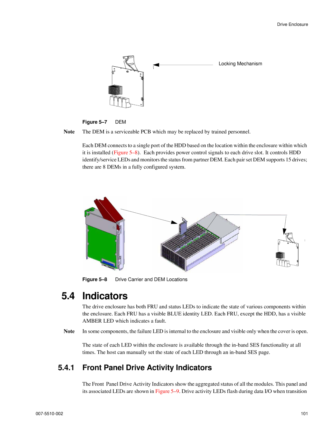
Locking Mechanism
Figure 5–7 DEM
Note The DEM is a serviceable PCB which may be replaced by trained personnel.
Each DEM connects to a single port of the HDD based on the location within the enclosure within which it is installed (Figure
Figure 5–8 Drive Carrier and DEM Locations
5.4 Indicators
The drive enclosure has both FRU and status LEDs to indicate the state of various components within the enclosure. Each FRU has a visible BLUE identity LED. Each FRU, except the HDD, has a visible AMBER LED which indicates a fault.
Note In some components, the failure LED is internal to the enclosure and visible only when the cover is open.
The state of each LED within the enclosure is available through the
5.4.1Front Panel Drive Activity Indicators
The Front Panel Drive Activity Indicators show the aggregated status of all the modules. This panel and its associated LEDs are shown in Figure
101 |