4.Remove the module’s thumbscrews, then slide the module out of the bay.
5.Slide the module into the bay making sure it is fully inserted. Install the two thumbscrews to secure it.
6.Turn on the power switch. Check that the Status LED is green, indicating that the module is operating normally.
7.Replace the cover panel (if necessary).
4.2.1.2Fan Failure
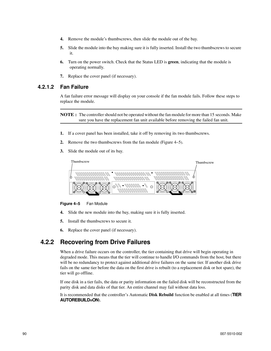
A fan failure error message will display on your console if the fan module fails. Follow these steps to replace the module.
NOTE : The controller should not be operated without the fan module for more than 15 seconds. Make sure you have the replacement fan unit available before removing the failed fan unit.
1.If a cover panel has been installed, take it off by removing its two thumbscrews.
2.Remove the two thumbscrews from the fan module (Figure
3.Slide the module out of its bay.
Thumbscrew |
|
|
|
|
|
|
|
|
| Thumbscrew | |||
|
|
|
|
|
|
|
|
|
|
|
|
|
|
|
|
|
|
|
|
|
|
|
|
|
|
|
|
|
|
|
|
|
|
|
|
|
|
|
|
|
|
|
|
|
|
|
|
|
|
|
|
|
|
|
|
|
|
|
|
|
|
|
|
|
|
|
|
|
|
|
|
|
|
|
|
|
|
|
|
|
|
|
|
Figure 4–5 Fan Module
4.Slide the new module into the bay, making sure it is fully inserted.
5.Install the thumbscrews to secure it.
6.Replace the cover panel (if necessary).
4.2.2Recovering from Drive Failures
When a drive failure occurs on the controller, the tier containing that drive will begin operating in degraded mode. This means that the tier will continue to handle I/O commands from the host, but there will be no redundancy to protect against additional drive failures on the same tier. If another disk drive fails on the same tier before the data on the first drive is rebuilt (to a replacement disk or hot spare), the tier will go offline.
If one disk in a tier fails, the data or parity information on the failed disk will be reconstructed from the parity disk and data disks of that tier. An entire channel may fail without data loss.
It is recommended that the controller’s Automatic Disk Rebuild function be enabled at all times (TIER AUTOREBUILD=ON).
90 |
|
