Table | I/O Module LEDs |
|
|
|
| |
|
|
|
|
|
|
|
|
| I/O Module | Amber | OFF | •No Faults present | •Off |
|
| Fault |
| ON | I/O Fault |
|
|
|
|
|
|
|
|
|
| I/O Module | Blue | ON | •Receiving SES | •Off |
|
| Identity |
| OFF | Command |
|
|
|
|
|
| Not receiving SES |
|
|
|
|
|
| Command |
|
|
|
|
|
|
|
|
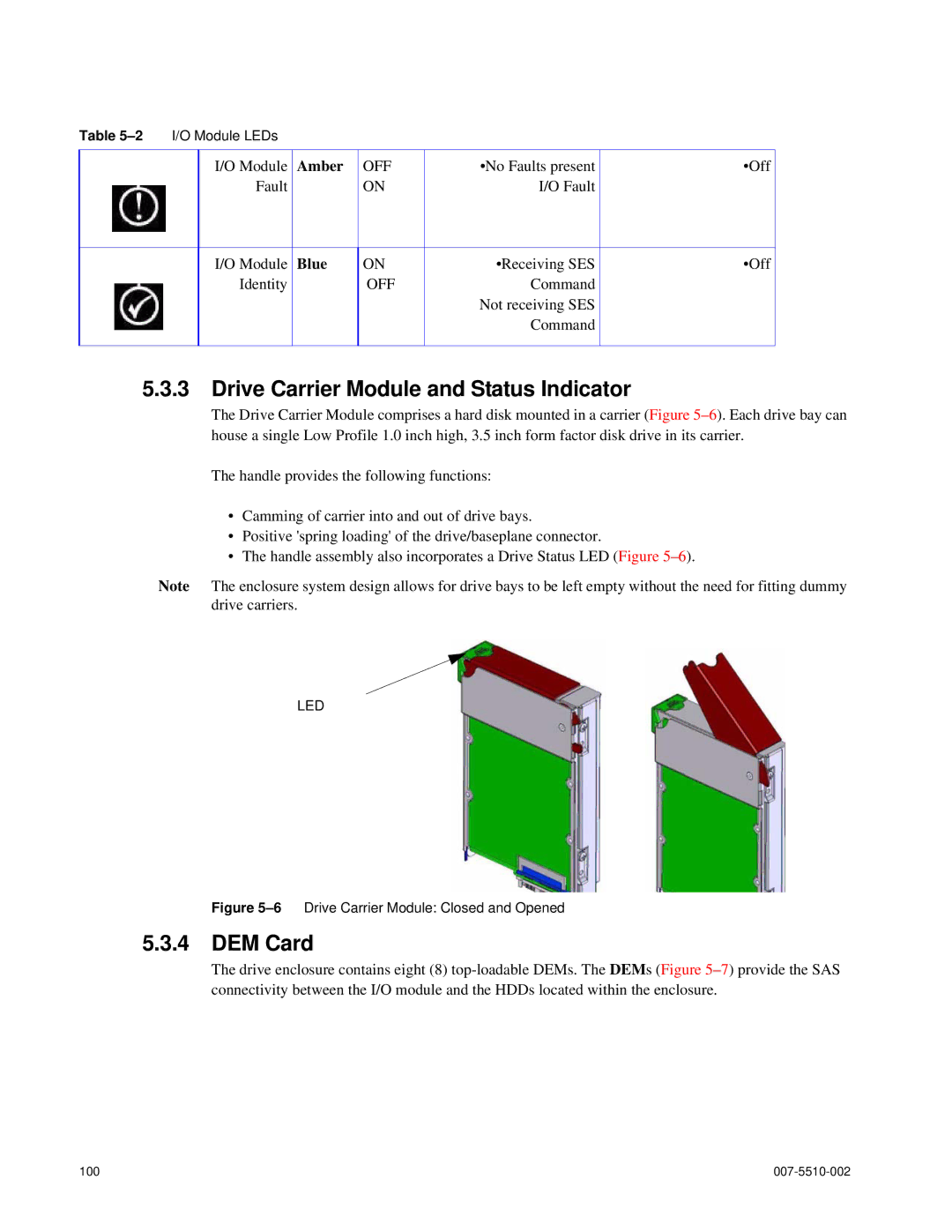
5.3.3Drive Carrier Module and Status Indicator
The Drive Carrier Module comprises a hard disk mounted in a carrier (Figure
The handle provides the following functions:
•Camming of carrier into and out of drive bays.
•Positive 'spring loading' of the drive/baseplane connector.
•The handle assembly also incorporates a Drive Status LED (Figure
Note The enclosure system design allows for drive bays to be left empty without the need for fitting dummy drive carriers.
LED
Figure 5–6 Drive Carrier Module: Closed and Opened
5.3.4DEM Card
The drive enclosure contains eight (8)
100 |
|