Table | Drive Enclosure Configuration | |
|
|
|
Module |
| Location |
|
| |
Power Cooling Modules (PCM) | Two (2) PCMs must be fitted. Full power and cooling redundancy | |
|
| is provided while a faulty module is replaced. Install the PCMs in |
|
| lower rear bays A and B. |
|
| Note: Rear bays are numbered from A and B starting from the |
|
| left when viewed from the back. |
|
|
|
I/O Module |
| One or two I/O modules should be Installed in the upper rear bays |
|
| A & B. |
|
| Note: If only one module is installed, it should be fitted in |
|
| Module Location A and a blank plate must be fitted |
|
| over the unused bay. |
|
|
|
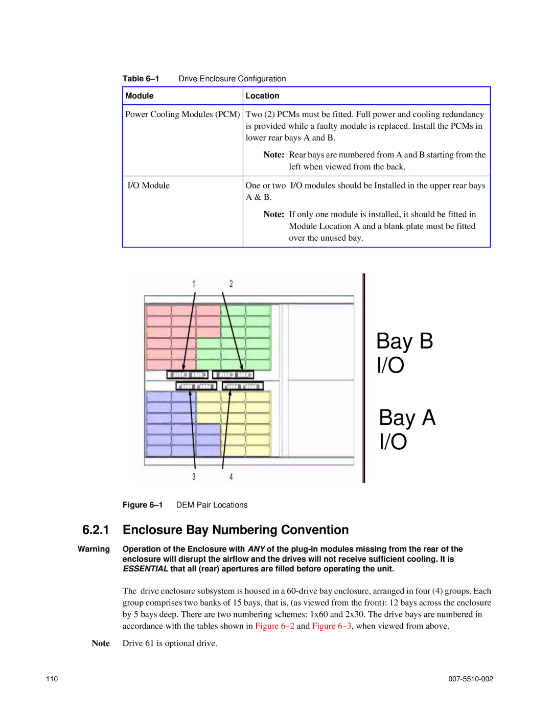
Bay B
I/O
Bay A
I/O
Figure 6–1 DEM Pair Locations
6.2.1Enclosure Bay Numbering Convention
Warning Operation of the Enclosure with ANY of the
The drive enclosure subsystem is housed in a
Note Drive 61 is optional drive.
110 |
|