|
|
|
|
| Drive Enclosure |
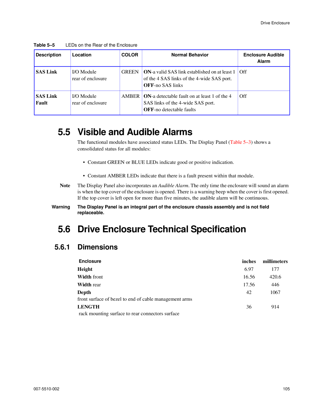
Table | LEDs on the Rear of the Enclosure |
|
| ||
|
|
|
|
|
|
Description |
| Location | COLOR | Normal Behavior | Enclosure Audible |
|
|
|
|
| Alarm |
|
|
|
|
|
|
SAS Link |
| I/O Module | GREEN | Off | |
|
| rear of enclosure |
| of the 4 SAS links of the |
|
|
|
|
|
| |
|
|
|
|
|
|
SAS Link |
| I/O Module | AMBER | Off | |
Fault |
| rear of enclosure |
| SAS links of the |
|
|
|
|
|
| |
|
|
|
|
|
|
5.5 Visible and Audible Alarms
The functional modules have associated status LEDs. The Display Panel (Table
•Constant GREEN or BLUE LEDs indicate good or positive indication.
•Constant AMBER LEDs indicate that there is a fault present within that module.
Note The Display Panel also incorporates an Audible Alarm. The only time the enclosure will sound an alarm is when the top cover of the enclosure is opened. There is a warning beep when the cover is first opened. If the top cover is left open for more than five minutes, the audible alarm will be continuous.
Warning The Display Panel is an integral part of the enclosure chassis assembly and is not field replaceable.
5.6Drive Enclosure Technical Specification
5.6.1Dimensions
Enclosure | inches | millimeters |
Height | 6.97 | 177 |
Width front | 16.56 | 420.6 |
Width rear | 17.56 | 446 |
Depth | 42 | 1067 |
front surface of bezel to end of cable management arms |
|
|
LENGTH | 36 | 914 |
rack mounting surface to rear connectors surface |
|
|
105 |