Multiserver
Multiserver
Trademarks
Table of Contents
Table of Contents
Bench Configuration and Testing
Getting Started
Testing Asynchronous Data Channels
Link Configuration
Using Modems with the Interconnect Link
Data-Channel Configuration
Switching Configuration
Administration
Diagnostics
LCD/Keypad
Appendix a Worksheets
Appendix B Cabling Diagrams
Appendix C Defaults
Appendix F Device Applications
Appendix E Indicators
Appendix D Messages
Physical Specifications
Specifications
Performance Specifications
Multiserver 5000 Base Unit
Multiserver Async Channel Characteristics
Sync Channel Characteristics
MS1 Expansion Module-Async Only
Configuration DCE Speed
Expansion Modules MS5 Expansion Module Sync/Async
MX215C
MS1 Voice/Fax Cards
General Specifications
Analog Specifications
Signaling Specifications
Digital Specifications
MS1 56K CSU/DSU Module
MS RLB Module
Converter/DCE
MS1 NMS Module
MS1 V.35 Converter/DCE
Introduction
LAN
Feeder Muxes
Module
LCN300A
MS1 Voice/Fax Card
CommPak
Expansion Modules
MS1 56K CSU/DSU Module MT150C
11 MS1 Rackmount Kit RM220
MS1 NMS Module MX227C
MS1 V.35 Converter/DCE MX226
Documentation
Manual Text Conventions
Bold
Multiserver
Network Design and Topologies
Initial Considerations
Nodes and Hubs
Default Node Numbers and Node IDs
Worksheets for the Network
Syntax for Node Numbers and IDs
Local Hub Group
Point-to-Point Switching Topology
Examples of Network Designs
Typical Point-to-Point, Dual Link with Load Balancing
Typical String Network
Typical Star Application
10. Typical Distributed-Star Application
Base-Unit Installation
Check Contents
LCD Display
CommPak Cartridge Installation and Removal
Power Up the Unit
Behind it
Checking the CCM Indicators
LCD/Keypad Information if you wish to stop
CCM Indicator LEDs
Channel numbers are assigned to all the ports on
Module and Channel Nomenclature
CCM Board. The front-panel of the unit is to the left
Module Installation
Module Stacking Order
Module-Location Switch Settings
Inter-Module Stacking Connectors
Inter-module stacking connectors
Disassembly Procedures
Blank Back Panel
Remove the cover after taking out four fastening screws
Remove any blank panels
CEM, VOICE/FAX CARD, or CSU/DSU Module
Installation Procedures
11. Installing the CCM
Ports
13. Reinstalling spacers
15. The front and back of the cover
Module Installation
Converters Optional Equipment
Getting Started
Connecting an Ascii Terminal
Async Terminal Settings
Multiserver Base Unit Location
Command Facility
Command Facility Main Menu appears
Disconnect message is displayed
There is no default password. Just press cr
Press cr. At the Enter Class prompt, enter $CMD
Reset Defaults
Key
Name the Local Node
Begin by pressing cr
Switch S1 on the NMS Module
Quick Setup
Installing and Configuring the Link
Switching Control Switching Controls Force Connect ALL
Bench Configuration and Testing
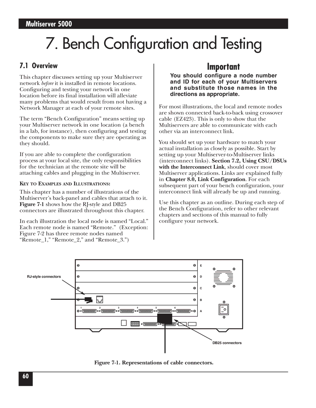
Overview
Bench Configuration and Testing
Using CSU/DSUs with the Interconnect Link
Bench Configuration and Testing
Bench Configuration for a Sync Data Channel
Sync Data Channel
Async terminal Port A6
Testing Asynchronous Data Channels
Asynchronous Terminal Settings
Local Multiserver
Testing the RLB Module
THICKNET, 10BASE-T, and Fiber
Voice/Fax Channels
Force Connect
Avoid Node Duplication
Link Configuration
Types of Links
Assign a Port for Each Link
Port Configuration
Multiserver 5000 CCM Default Port Configurations
Interconnect Link
Screen will display the following prompt
Next, select option 3 from the remote Command Facility menu
Enter the node ID. Press cr
Mux Link
Enter NODE-ID # ###
Select option 5 on the Port Configuration Menu
X.21 Link
Option Default Description
X.21 Link Parameters
Same number as before
Link Configuration Description
See -2, X.21 Link
Review Link Configuration
Data-Channel Configuration
An example might be NEWYORK/A4
Following protocol menu will appear
Configure the port for sync
Synchronous Channels
Sync Protocol Options
Option Description
Sync Channel Characteristics Used for Each Sync Protocol
DLC
Sync Channel Characteristics
Option Protocol Default Description
DLC To DTE
DLC None
Data-Channel Configuration
Configuration Description of Use
Synchronous Clocking
DTE
DCE
Asynchronous Channels
Async Channel Channel Characteristics
Asynchronous Channel Characteristics
DC1
Autobaud Rates
10. Multiserver Bit Conversion
Async Channel Channel Features
11. Asynchronous Channel Features
Asynchronous-Channel Switching Parameters, EIA
100
12. Asynchronous Channel Extended Features
Copy Channel Parameters
Review Data-Channel Configuration
104
Data-Channel Configuration
Connecting Data Channels Cables
Switching Control
Switching Configuration
Switching Control
107
108
Prompt From the Command Facility Main Menu, select
All
Force-Connecting a Range
Disconnecting ranges, see .3, Force Connecting a Range
Synchronous Connections
Ports
Information
Asynchronous Connections
Classes, for class
113
Matching Capability for Asynchronous Channels
Asychronous-Channel Switching Parameters
Menu options is discussed in Table
Switching Parameters
Asynchronous Channels, and -11, Asynchronous Channel
117
Classes
Local and Remote Hub Groups
119
User is connected to the class
Enter the primary class name selected. Press cr
Class Configuration
122
123
Connect Protocol Details
Disconnect Sequence
Initiated by device Device initiates
Port Contention/Queueing
Call Completion Receiving port
10.11 X.21 Switching Considerations
Configure the port for DTR and assign it to the class
128
Async Channel
Administration
Reset
Menu-flow diagram for LCD/Keypad resets
Each type of reset is described in Table
Reset Options
Options of this menu are detailed in -2on the following
Command Mode
Command Mode menu will appear
Command Mode
Selection of loopback tests. See .3, Async Channel Loopback
Configuring the Command Facility
Administration
Command Facility Configuration
137
138
139
If the port or range selected is all async, the system
Messages
Enter the node ID and channel number or range of channels
Special Message Characters
Max Option Default Char Description
Dialog Messages
143
Network Security
Three menu options are detailed in -6, which is on the next
Password Menu
Status/Statistics
Status/Statistics
147
148
149
150
151
152
153
Link Configuration , for
Link Administration
Channel Administration
Option Description
Classes, for more information
Switching Administration
Queue. See Section
156
Terminate Test
Diagnostics
Self-Test
There are four test options available
158
System Diagnostics in the Command Facility
When this option is selected, the following menu appears
160
Sync Channel Loopback
Enter the channel to be tested. Press cr
This test causes all of the LED indicator lights to
After the test is initiated, the Command Facility
Terminal will be returned to the Command Facility
Following menu will appear
Testing the Network
Integral CSU/DSU
164
LCD/Keypad
General LCD/Keypad Information
166
Multiserver LCD/Keyboard Menu Flow Chart
Menu Tree
Banner Message Display
LCD Banner Display
Review System Message Log
Administration
Reset
Menu Functions
170
This menu offers the following options
Diagnostics
Press the EXEcute key again and the Multiserver will reset
This menu offers the following test options
Input Level Monitors the level of the incoming
173
Configuration
Prom #
Appendix a Worksheets
Worksheet for Planning Node Numbers and Node IDs
Remote
Synchronous Protocol and Channel Worksheet
179
Asynchronous Channel Characteristics Worksheet
OFF
Asynchronous Channel Features Worksheet
183
Asynchronous Channel Extended Features Worksheet
Record of Asynchronous Classes
Switching Parameters Worksheet
Command Facility Parameters Worksheet
Display Messages Worksheet
Voice/Fax Parameters Worksheet
Record of Passwords
Appendix B Cabling Diagrams
Cabling for the CCM and 6-Channel CEMs
193
194
195
196
197
Cabling for the 12-Channel CEM
199
200
201
Cabling for the 12-Channel CEM with Line Drivers
203
Cabling for the MS1 56K CSU/DSU Module
Cabling for the NMS Module
Cabling for Converters
207
208
209
Figure B-13. Tandem Cable Diagram
Cabling for Use with Tandem
Multiserver and Feeder Mux Default Node Numbers and IDs
Appendix C Defaults
System Administration
Port Configuration
Command Facility Parameters
Dialog Messages
Channel Features
Asynchronous Channel Configuration
Channel Characteristics
Extended Features
Ascii Bisync and Ebcdic Bisync
DLC
Synchronous Channel Configuration
Sync-Pad
Sync
Micom Voice
Fast Packet
Interface
Voice/Fax Module
KTS Interface
OPX Interface
Voice/Fax Switching Parameters
Voice/Fax Node Parameters
Log Printer Port
Command Port
NMS Module
Appendix D Messages
Screen Display Messages
Screen Display Messages
Message
224
Screen Display Messages
226
227
228
229
230
231
232
Message Message Type Explanation
Node ID n/channel number c
Class name or Matrix if matrix switching is used
LCD Messages
LCD Messages
236
LCD Messages
238
Appendix E Indicators
Definition Off Flashing
Table E-2. CCM Indicator LEDs
241
LED
243
244
Appendix F Device Applications
Tandem
Table F-1. Spool Mode
Type of Terminal
Appendix G Rackmount Installation
Figure G-1. Clip nut assembly for rack
248
Upgrade Information
Appendix H Additional Infomation
250
Appendix H Additional Information
Glossary
Glossary
Configuration switch group See switch group
254
255
256
EBCDIC, Extended Binary Coded Decimal
ISU, integrated service unit An integral interface
FDX See full-duplex
258
259
260
PTT, Post, Telephone, and Telegraph
SF, single frequency See tone signaling
Single frequency See tone-signalling Slow busy signal
262
263
Multiserver LCD/Keyboard Menu Flow Chart
Menu Flow Diagram
Park Drive Lawrence, PA 15055-1018 724-746-5500 Fax