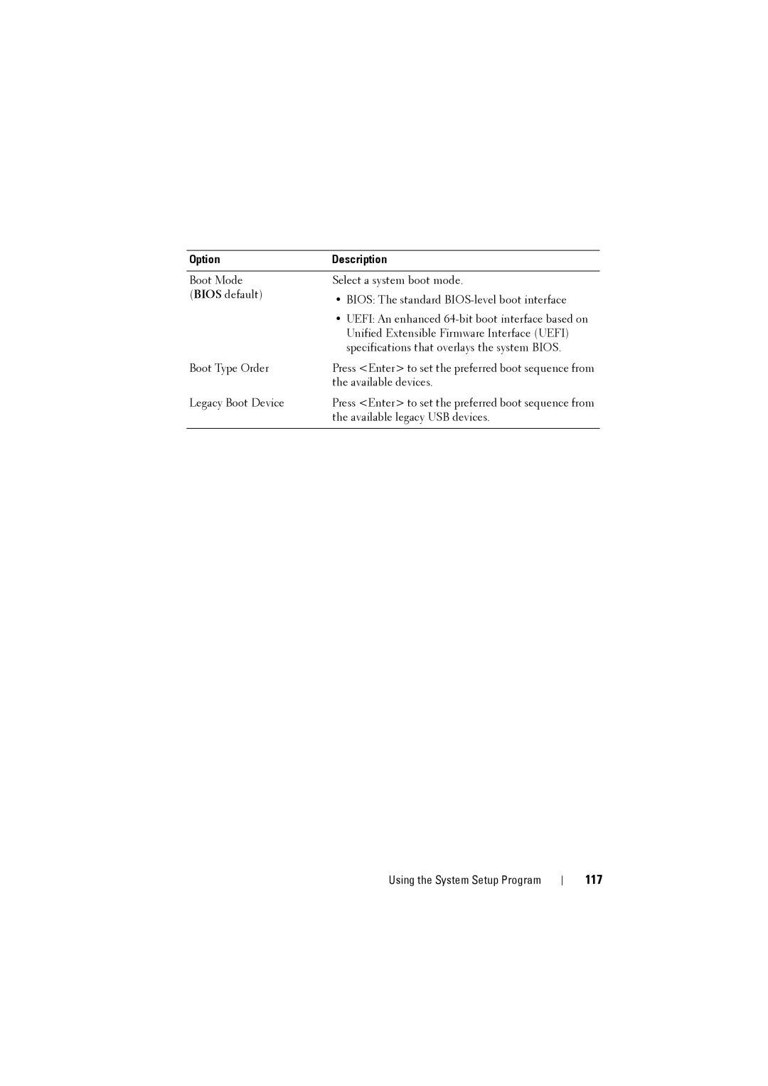
Main
Notes, Cautions, and Warnings
Contents
1 About the System . . . . . . . . . . . . . . . . . . 11
2 Using the System Setup Program . . . . . 67
Page
3 Installing System Components . . . . . . . 187
4 Rack Mount Configuration . . . . . . . . . . 221
5 Troubleshooting. . . . . . . . . . . . . . . . . . . 251
Page
7 Jumpers and Connectors. . . . . . . . . . . . 285
8 Getting Help. . . . . . . . . . . . . . . . . . . . . . 289
Index . . . . . . . . . . . . . . . . . . . . . . . . . . . . . . 291
About the System
Accessing System Features During Startup
Front-Panel Features and Indicators
NOTE:
Page
Back-Panel Features and Indicators
Page
NOTE:
18
Server Enclosure Indicator Codes
Page
NIC Indicator Codes
Page
Sled Bay Numbering
Fan Bay Numbering
Page
Page
Sled Features
Compute Sleds
Page
Page
Page
Page
Page
Page
Page
Storage Sleds
Page
Page
Page
Page
Page
Page
Page
POST Error Codes
Collecting System Event Log for Investigation
Page
Page
Page
Page
Page
Page
Page
50
System Event Log
Processor Error
Message: Processor Sensor, IERR error, Processor 1
Memory Ecc
Message: Memory Sensor, Correctable ECC error, SBE warning threshold, CPU1 DIMM_A1
Page
PCIe Error
Message: Critical Interrupt Sensor, PCI PERR, Device#, Function#, Bus#
54
IOH Core Error
Message: Critical Interrupt Sensor, Fatal Error, xxxx bit, QPI[0] Error
SB Error
Message: Critical Interrupt Sensor, Correctable, MCU Parity Error
56
POST Start Event
Message: System Event, POST starts with BIOS xx.xx.xx
POST End Event
58
POST Error Code Event
Message: System Firmware Progress, POST error code: UBLBh.
BIOS Recovery Event
ME Fail Event
SEL Generator ID
BMC
Page
Page
Page
Page
Other Information You May Need
Using the System Setup Program
System Setup Menu
System Setup Options at Boot
Using the System Setup Program Navigation Keys
General Help
Console Redirection
Enabling and Configuring Console Redirection
Page
Page
Page
Page
Main Menu
Main Screen
System Settings
NOTE:
Page
Advanced Menu
Power Management
Power Management
NOTE:
80
Chassis Power Management
NOTE:
Page
Page
Boundaries of PSU Configuration
84
Scroll to this item and press <Enter> to view the following screens.
NOTE:
86
NOTE:
Emergency Throttling
CPU Configuration
CPU Configuration
90
NOTE:
Prefetch Configuration
Memory Configuration
Page
94
NOTE:
Page
SATA Configuration
Page
PCI Configuration
PCI Configuration
NOTE:
Page
Embedded Network Devices
Page
Active State Power Management Configuration
Page
USB Configuration
USB Configuration
Security Menu
108
WARNING:
NOTE:
Server Menu
Page
Set BMC LAN Configuration
Page
Remote Access Configuration
Page
View System Log
Boot Menu
Page
Exit Menu
Exit Options
Page
Command Line Interfaces for System Setup Options
Page
Page
Page
Page
Page
Page
Page
Page
Page
Page
Page
Page
Page
Page
Page
Page
Page
Page
Page
Page
Page
Page
Page
144
NOTE:
IPMI Command List
Page
Page
Page
Page
Page
Page
Page
Page
Power Management Settings
Page
SNMP
About MIB and Traps
SNMP Support for the Server Enclosure Fan Controller Board
Page
158
FCB Firmware Behavior
The following table lists the FCB firmware behavior.
Page
Page
FCB SNMP MIB
Page
Page
Page
Using the System Setup Program 165
Table 2-22. FCB SNMP MIB
166
NOTE:
SNMP Support for the External PDU Power Management Controller Board
Page
PMC Firmware Behavior
The following table lists the PMC firmware behavior.
Page
PMC SNMP MIB
Page
Page
Page
Page
Page
Page
Page
Page
Page
Page
Page
Page
Page
Page
Page
Installing System Components
Safety Instructions
About the Illustrations
Recommended Tools
Inside the System
Sled Blank
Removing a Double-Wide Sled Blank
Installing a Double-Wide Sled Blank
Removing a Single-Wide Sled Blank
Installing a Single-Wide Sled Blank
Compute Sleds
Removing a Compute Sled
Page
Installing a Compute Sled
Storage Sled
Removing a Storage Sled
Installing a Storage Sled
Power Sled
Page
198
Inside a Power Sled
Removing a Power Sled
Page
Installing a Power Sled
Removing the PSU1/3 Module Assembly
202
Installing the PSU1/3 Module Assembly
Removing the PSU2/4 Module Assembly
Installing the PSU2/4 Module Assembly
Removing the PSU Module
Installing the PSU Module
Fan Modules
Removing a Fan Module
Installing a Fan Module
Front Panel Board
Removing the Front Panel Board
Installing the Front Panel Board
Fan Controller Board
Removing the Fan Controller Board
Installing the Fan Controller Board
Backplane/Fan Bay Cage
Removing the Backplane/Fan Bay Cage
Page
Page
Page
Installing the Backplane/Fan Bay Cage
PDU Power Supply
PDU Power Supply Indicator Code
Removing a PDU Power Supply
Page
Installing a PDU Power Supply
Page
Rack Mount Configuration
Installation Guidelines
Recommended Tools
Installation Tasks
Installing the Tool-Less Rail Solution in the Rack
Page
Page
Page
Page
Removing Sled Modules from the Server Enclosure
Installing the Server Enclosure into the Rack
Page
Replacing Sled Modules in the Server Enclosure
Installing the External PDU into the Rack
Page
Page
Page
Page
FRONT
Connecting the Power Cables
Connecting the Power Cables to the Server Enclosure with Internal Power Source
Connecting the Power Cable to the Server Enclosure with External Power Source
Connecting the Server Enclosure to a Rack PDU
Page
5
Close the cable cover and secure to the PDU. See Figure4-15.
Connecting a Network Switch to a Rack PDU
Connecting the PDU to the Network
Page
Page
Powering Up the Systems
Page
Page
Page
Page
Troubleshooting
Safety FirstFor You and Your System
Installation Problems
Troubleshooting System Startup Failure
Troubleshooting External Connections
Troubleshooting the Video Subsystem
Troubleshooting a USB Device
Troubleshooting a Serial I/O Device
Troubleshooting a NIC
Troubleshooting a Wet Enclosure
Troubleshooting a Damaged Enclosure
Troubleshooting 257
Troubleshooting Enclosure Fan Modules
Fan Module (Fan Controller Firmware) Thermal Behavior Per Sled
Table 5-1. Fan Module (Fan Controller Firmware) Thermal Behavior Per Sled
258
Fan Controller Firmware Response
Table 5-2. Case Scenario 1
Table 5-1. Fan Module (Fan Controller Firmware) Thermal Behavior Per Sled
Page
Page
Page
Troubleshooting Cooling Problems
Page
Page
Air Inlet Temperature Threshold Settings
NOTE:
266
NOTE:
Troubleshooting Sled Components
Troubleshooting System Memory
Page
Troubleshooting a Hard-Drive
Troubleshooting Expansion Cards
Troubleshooting Processors
Troubleshooting the System Board
Troubleshooting the System Battery
IRQ Assignment Conflicts
Page
Updating Firmware Images and Monitoring the PDU Power Status
Verifying and Updating the Fan Controller Board Firmware Via the Compute Sled
Viewing the Fan Controller Board Firmware Version Information
Updating the Fan Controller Board Firmware
Verifying and Updating the Fan Controller Board Firmware Via SNMP
Before You Begin
Checking FCB Indicators
Resetting the FCB Network Connection
Viewing or Changing the FCB Configuration Information
Configuring the SNMP Traps
Updating the FCB Firmware
Viewing the FCB Firmware Version Information
Monitoring the External PDU Power Status and Updating the PDU PMC Firmware
Before You Begin
Checking PDU Indicators
Resetting the PDU Network Connection
Viewing or Changing the PMC Configuration Information
Configuring the SNMP Traps
Updating the PMC Firmware
Viewing the PMC Firmware Version Information
Jumpers and Connectors
Server Enclosure Boards
Front Panel Board Connectors
286
Fan Controller Board Connectors
Power Management Board Connectors
Page
Getting Help
Contacting Dell
Page
Index
A
B
C
D
I
M
P
R
S
Page
T