Server Enclosure Indicator Codes
The indicators on the front and back of the server enclosure displays operational status of the enclosure, fan modules, and chassis controller boards.
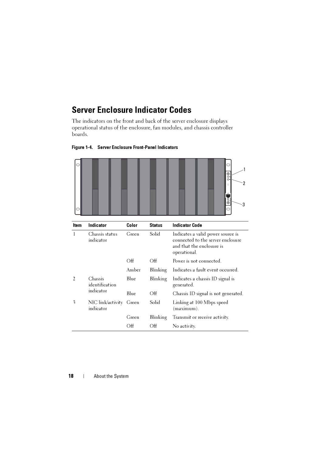
Figure 1-4. Server Enclosure Front-Panel Indicators
Item | Indicator | Color | Status | Indicator Code |
|
|
|
|
|
1 | Chassis status | Green | Solid | Indicates a valid power source is |
| indicator |
|
| connected to the server enclosure |
|
|
|
| and that the enclosure is |
|
|
|
| operational. |
|
| Off | Off | Power is not connected. |
|
| Amber | Blinking | Indicates a fault event occurred. |
2 | Chassis | Blue | Blinking | Indicates a chassis ID signal is |
| identification |
|
| generated. |
| indicator | Blue | Off | Chassis ID signal is not generated. |
|
| |||
3 | NIC link/activity | Green | Solid | Linking at 100 Mbps speed |
| indicator |
|
| (maximum). |
|
| Green | Blinking | Transmit or receive activity. |
|
| Off | Off | No activity. |
|
|
|
|
|
18
About the System