Page
Page
Page
Preface
Page
Table of Contents
Parameters
Troubleshooting
Digital Keypad Operation and Start Up
Appendix a Specifications Appendix B Accessories
Fault Code Information and Maintenance
Appendix C How to Select the Right AC Motor Drive
Introduction
Receiving and Inspection
Example for 5HP/3.7kW 3-phase 230V AC motor drive
Nameplate Information
Model Explanation
5HP/0.75-3.7kW Frame B 15HP/5.5-11kW Frame C
Series Number Explanation
Drive Frames and Appearances
15-30HP/11-22kW Frame D 40-100HP/30-75kW Frame E
Preparation for Installation and Wiring Ambient Conditions
Transportation
Operation
Storage
Remove Keypad
Remove Front Cover
Step
Lifting
Dimensions
Introduction
Introduction
Introduction
Frame E
This page intentionally left blank
Installation and Wiring
RL1 UT1 SL2 VT2 TL3 WT3
Wiring
For models of VFD-VE Series 20HP/15kW and above
FWD REV MI1 MI2 MI3 MI4 MI5 MI6 DCM
External Wiring
Main Circuit Main Circuit Connection
+2/B1
NFB
Brak e res istor
Motor
Terminals +1, +2 for connecting DC reactor
Mains power terminals R/L1, S/L2, T/L3
Output terminals for main circuit U, V, W
Forward running
Refer to Appendix B for the use
+2/B1 Brake resistoroptional Brake unitoptional
Spec ial braking resis tor/unit
Grounding terminals
Main Circuit Terminals
Models Wire Torque Wire Type
Control Terminals
Position of the Control Terminals
OFF
FWD
DFM
MRA
MCM
Terminal Terminal Function Factory Settings Sink
MO1
MO2
ACM
AFM
Analog input terminals AVI, ACI, AUI, ACM
AVI/ACI/AUI ACM
AWG 0.3-2.1mm
Frame Torque Wire
General
Page
Descriptions
Display Message
Display Message Descriptions
External Fault
Displays the selected parameter
Displays the actual stored value of the selected parameter
Start
How to Operate the Digital Keypad KPV-CE01
To copy parameters
LCD
Dimension of the Digital Keypad
Reference Table for the LCD Display of the Digital Keypad
Operation Method
External signal
Start-up Preparations before Start-up
Communication Communication address definition
JOG
Check following items
Trial Run
Digital Keypad Operation and Start Up
This page intentionally left blank
Parameters
Group 0 System Parameters
Summary of Parameter Settings
Parameter can be set during operation
Time Unit for Unit 0.01 second 00-14
Group 1 Basic Parameters
01-36 1st Output Voltage 230V 0.1V~255.0V
RUN/STOP, REV/FWD
Group 2 Digital Input/Output Parameters
MOA
Width of the Desired
AUI
Group 3 Analog Input/Output Parameters
~200.0% 100.0
Group 4 Multi-Step Speed Parameters
Group 5 Motor Parameters
Group 6 Protection Parameters
Parameters
06-28 Electronic Thermal 30.0~600.0 sec
Speed Search 07-10 Base-block Speed Stop operation
Group 7 Special Parameters
07-29 High Torque Offset
Group 8 High-function PID Parameters
08-32 Tension PID P2
100.0 Feedback
Group 9 Communication Parameters
09-20 Block Transfer
Group 10 Speed Feedback Control Parameters
Explanation Settings
Group 11 Advanced Parameters
Version
Version Differences
Crane function
Low-voltage during constant speed
Version Group 0 System Parameters
Version 2.02, the parameters are from Pr.08-00 to Pr.08-15
New settings 44~50 for Pr.02-00~Pr.02-06 and new parameter
02-35 Multi-function Output
Setting Reserved 02-43 Zero-speed Level ~65535 rpm Motor
05-03 Rated speed of Motor
Setting 08-00 Input Terminal for PID No function Feedback
PID
Switch Level for Smart ~100.0% according to Pr.08-26
Setting 10-04 ASR Auto Speed
00-01
Description of Parameter Settings
00-00
00-03
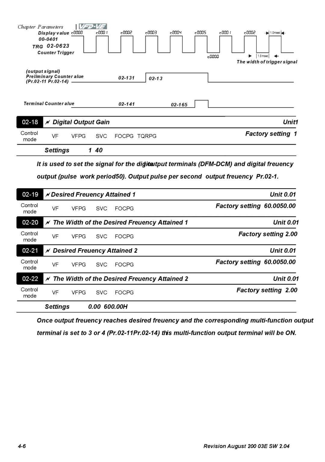
Factory setting
Start-up Display Selection
00-04
00-04Content of Multi-Function function Display Settings
MO2 MO1 MRA
MI9 MI8 MI7 MI6 MI5 MI4 MI3 MI2 MI1 REV FWD
00-08
00-06
00-07
00-08 00-07
No password set or successful input in Pr
00-09
Factory setting 100%
Energy Saving Gain Unit
00-10
Optimal Acceleration/Deceleration Setting
Settings Constant Torque 100% Variable Torque 125%
00-12
Constant/Variable Torque Selection
00-15 00-16
00-14
00-17
230V/460V Series
Auto Voltage Regulation AVR Function
00-18
00-19
Auto Energy-saving Operation
Stop Method Factory setting
Source of the Master Frequency Command Factory setting
Settings Ramp to stop Coast to stop
00-20
Reverse Operation
00-23
01-01
01-00
01-35
01-02
01-37
01-04
01-38
01-05
01-41
Settings 00~600.00Hz
01-42
01-09
Pr.01 =Fl ow =Fc md
FcmdFmi n Pr.01
60Hz =Fl ow
Flow
Output Frequency Upper Limit Unit
01-10
01-11
Output Frequency Lower Limit Unit
01-13
01-12
01-14
01-15
01-24 01-25 01-26
01-22
01-23
01-28
01-27
01-29
01-30
Fout 01-34=0 01-34=1 01-34=2 Fmin 01-07 Frequency command
02-00 Control Circuits of the External Terminal
RUN/STOP, REV/FWD
FWD/STOP
REV/STOP
02-30
Multi-Function Input Command
Parameters
As long as the ON/OFF status is restored, the speed-tracing
Settings Functions Descriptions
JOG are included. Refer to Pr -00~04-29
Function could still be operated
Command form ACI Force to be ACI Operation speed
Command form AVI Force to be AVI Operation speed
OFF FOC+PG speed control mode
When it is ON, the drive will operate by 1st V/f
Enable multi-step
Execute position control
Enable position control
Motor Frequency 10-19 Feedbac k 10-00 10-01
RUN
Change from speed command to position command. It is
When this function is enabled, the pulse of PG card will
02-07
UP/DOWN Key Mode
Serial position input
02-10
02-09
MI9 MI8 MI7 MI6
MI4 MI3 MI2 MI1 REV
02-14
02-13
02-35
02-36
Settings Functions Descriptions
Indication Baseblock Active when the warning is detected
Settings Functions Descriptions
When the error between PID target value and PID feedback
It will be OFF when brake delay time exceeds Pr.02-31
For error treatment of tension PID feedback
Speed Attained
Multi-output Direction Unit1
Reserved Example of crane function
02-15
02-17
02-16
02-19
02-18
02-20
02-21
Settings 000~65.000 Sec
Brake Delay Time Unit0.001
Output Current Level Setting for External Terminals Unit1
02-31
02-43
02-33
02-34
03-02
03-00
03-01
03-05
03-03
03-04
03-10
03-09
03-11
03-12
03-15
03-14
03-16
03-17
10~10V=0~100%
~10V=0~100%
~20mA=0~100%
03-22
03-19
03-25
03-20
04-01
04-00
04-02
04-03
MI4 MI3 MI2 MI1
05-00
05-02
05-01
05-03
05-04
05-07
05-06
05-10
05-12
Connection is finished Connection control
Full-load Current of Motor Unit 1%
05-13
05-14
05-15
05-18
05-17
05-19
05-22
05-25
05-24
05-26
05-27
05-32
05-29
05-31
Low Voltage Level Unit
06-00
06-01
Over-Voltage Stall Prevention Unit
06-04
06-02
06-03
06-06
06-05
Over-torque Detection Selection OT1
06-07
06-11
06-10
06-13
06-12
06-14
06-28
06-16
Load
06-15
Parameters
06-23
Fault code Bit0 Bit1 Bit2 Bit3 Bit4 Bit5 Bit6 Current Volt
06-24
06-25
Revision August 2008, 03VE, SW 103
ACE
Fault code Bit0 Bit1 Bit2 Bit3 Bit4 Bit5 Bit6
External fault input EF
Connection
PTC Positive Temperature Coefficient Detection Selection
06-29
06-30
06-32
06-31
06-33
06-34
07-01
07-00
07-02
07-03
Maximum Allowable Power Loss Time Unit
Momentary Power Loss Operation Selection
07-06
07-07
Baseblock Time for Speed Search BB Unit
07-08
Current Limit for Speed Search Unit
07-09
07-10
Auto Restart After Fault Unit
07-11
07-12
07-13
Decel. Time Selection for Momentary Power Loss DEB function
07-14
DEB Return Time Unit
Status 2 unexpected power off, such as momentary power loss
07-16
07-15
07-17
07-18
07-21
07-20
07-22
07-23
07-27
07-25
07-26
07-29
07-28
07-30
07-31
Emergency Stop EF & Forced Stop Selection
07-36
08-02
08-01
08-04
08-03
08-05
08-06
08-08
Feedback Signal Detection Time Unit
08-09
To 3600.0 sec
08-10
08-11
08-14
08-13
08-15
08-16
Line speed, speed mode
Open-loop, torque mode
08-23
08-22
08-24
08-26
08-28
Auto-tuning Tension PID
08-29
Tension PID P1 Unit
08-31
08-30
08-32
08-33
DCM AB2
DFM DCM
08-38
08-39
08-40
Settings To 3000.0 m/min
Pulse Number for Each Meter Unit
08-41
08-44
08-43
08-46
08-47
08-51
08-50
08-52
08-54
08-62
08-57
08-58
08-67
08-64
08-68
08-69
08-75
08-71
08-77
08-78
08-84
08-83
08-85
08-86
Communication Address
09-00
09-01
09-02
Ascii mode
Settings Modbus Ascii mode, protocol 7,N,1
09-03
09-04
STX
RTU mode
END
Data
Start
F7H
6FH
0FH
Address ‘0’ ‘1’ Function ‘3’ Starting data address ‘4’
Content
A0H
00B No function
Jog + Run
Ascii mode RTU mode
Command F
Code
C3H
A1H
09-06
09-05
09-07
09-08
09-10
09-09
09-11
09-12
09-15
09-14
09-16
09-17
10-00
Group 10 PID Control
Encoder Pulse
Fwdrev
10-03
10-02
10-04
10-05
10-12
10-09
10-10
10-14
10-13
10-15
FWD REV
10-17
10-16
10-18
10-19
10-21
10-20
10-22
10-23
10-27
10-26
10-28
10-29
Control Diagram fo r the Torque + Encoder
Speed
YES
11-00
System Control
11-02
11-01
11-03
11-11
Gain Value of Flux Weakening Curve for Motor Unit
11-05
11-07
11-06
11-08
11-09
11-13
11-12
11-14
11-15
11-18 APR Gain
11-17
11-19
11-20
Revision August 2008, 03VE, SW 165
Page
Over Current OC
Troubleshooting
Over Voltage OV
Ground Fault
Ground fault
Low Voltage Lv
Suitable power
Over Heat oH1, oH2, oH3
Reduce load or increase the power of AC motor drive
Overload
OL1/ OL2
Yes
Phase Loss PHL
Display of KPV-CE01 is Abnormal
Motor cannot Run
Motor Speed cannot be Changed
Motor does not Run as Expected
Motor Stalls during Acceleration
Environmental Condition
Electromagnetic/Induction Noise
Affecting Other Machines
Common Problems and Solutions
Fault Code Information
Provided for AC motor drive protection
Ground fault Not for protection of the user
Phase Loss
Heatsink
Igbt overheating
Overheating
Motor overheating
Phase error
Isum error
OC hardware error
OV hardware error
Brake resistor fault
Password is locked
Connection switch
Error
When slip exceeds
Reset
It will be displayed
Decrease the load if overload
Periodic Inspection
Maintenance and Inspections
Daily Inspection
One
Voltage Maintenance Check Items Methods and Criterion
Keypad Maintenance Check Items Methods and Criterion
Change of copper plate
Check Items Methods and Criterion
Daily
Visual, aural inspection and smell Or peculiar smell
Change fan Overheat
This page intentionally left blank
Appendix a Specifications
± 5%
Applicable
All Brake Resistors & Brake Units Used in AC Motor Drives
Model Vfdb Model and No. Torque
BR1K2W6P8
Prevent damaging the brake resistor
Decrease accordingly. Suggested cycle time is one minute
VFD Series
Dimensions are in millimeter
Dimensions and Weights for Brake Resistors
Order P/N BR500W030, BR500W100, BR1KW020, BR1KW075
Specifications for Brake Unit
189.5 200.0
Dimensions for Brake Unit
Dimensions are in millimeterinch
VFDB4132
Phase
No-fuse Circuit Breaker Chart
Smaller fuses than those shown in the table are permitted
Fuse Specification Chart
Model Line Fuse Input Output Bussmann P/N
VFD007V23A-2 JJN-10 VFD007V43A-2
AC Output Reactor Recommended Value
AC Reactor AC Input Reactor Recommended Value
Impedance
37.5 52.5 18.5 67.5 82.5 120 100 150 130 195
37.5 52.5 18.5 67.5 120 100 150 130 195 160 240
Fundamental Max Inductance mH Continuous Amps
May damage the mains circuit
Applications for AC Reactor
Silicon rectifier Powerreactor AC motor drive Reactor Motor
Diagram a
Zero Phase Reactor RF220X00A
Diagram B
Nominal Method
Input voltage DC Amps Inductance mh
DC Choke Recommended Values
AFM ACM AVI
Remote Controller RC-01
+10V
DCM MI5 FWD REV JOG VFD-VE
PG1 PG2
PG Card for Encoder EMV-PG01X
ABZ1
300m
70m Basic Wiring Diagram wiring
Voltage
Types of Pulse Generators Encoders
12V
EMV-PG01O
Terminal Descriptions Symbols
Types of Pulse Generators
PG OUT
70m
Z1, Z1 Phase or 2-phase input. Maximum 300kP/sec A2, A2
Wire Gauge 25mm2 AWG16 or above Basic Wiring Diagram
EMV-PG01O
Voltage
Z1, Z1 Phase input. Maximum 300kP/sec
Power source of EMV-PG01L
EMV-PG01L
Output Voltage +5V ±5% 200mA
Wire Gauge 25mm2 AWG16 or above Basic Wiring Diagram wiring
ABZ1 AB2
Complementary
AC Drives Model Number FootPrint
AMD-EMI Filter Cross Reference
10TDT1W4C
26TDT1W4C
Saddle on both ends Saddle on one end
Choose suitable motor cable and precautions
„ For models 5hp/3.7kW and less
Insulation level of motor 1000V 1300V 1600V
1000V 1300V 1600V 460VAC input voltage
230VAC input voltage
Appendix B Accessories
Order P/N RF015B21AA / RF022B43AA
Dimensions are in millimeter and inch
302 315
Order P/N RF022B21BA / RF037B43BA
Order P/N RF110B43CA
Order P/N 10TDT1W4C Order P/N 26TDT1W4C
Order P/N 50TDS4W4C Order P/N 100TDS84C
Order P/N 200TDDS84C Order P/N 150TDS84C
Order P/N 180TDS84C
Terminals Description
Power
Multi-function I/O Extension Card Functions
SO1-MCM
Terminals
SO2-MCM
MI7~MIB
Dimensions Wiring
This page intentionally left blank
Page
Speed Time Overload Starting Torque Ratings
Related Specification
Capacity Formulas
Starting capacity=
When one AC motor drive operates one motor
When one AC motor drive operates more than one motor
⋅ IM ≤ the rated current of AC motor drive a
General Precaution
Selection Note
Parameter Settings Note
Standard motor
How to Choose a Suitable Motor
Special motors
Power Transmission Mechanism
Pole-changing Dahlander motor
Motor torque
Motor
This page intentionally left blank