Functions & Installation 3. Installation
3.4Connection
CAUTION
This section indicates the connection of the Controller and the Teach Pendant.
Be sure to connect the cables of Controller and Teach Pendant properly. Do not allow unnecessary strain on the cables. (Do not put heavy objects on the cables. Do not bend or pull the cables forcibly.) The unnecessary strain on the cables may result in damage to the cables, disconnection, and/or contact failure. Damaged cables, disconnection, or contact failure is extremely hazardous and may result in improper function of the system.
Make sure that the pins are not bent when connecting the connector. Connecting the connector with the pin bent may cause malfunction and result in improper function of the system.
The connector connected to the end of the cable is a
3.4.1 Typical cable connection
The Teach Pendant and the Operator Panel is connected to TP/OP port of controller.
NOTE When nothing is connected to the TP/OP port, Emergency Stop status occurs to the Controller. When the Teach Pendant or the Operator Panel is not connected, connect the TP/OP bypass plug.
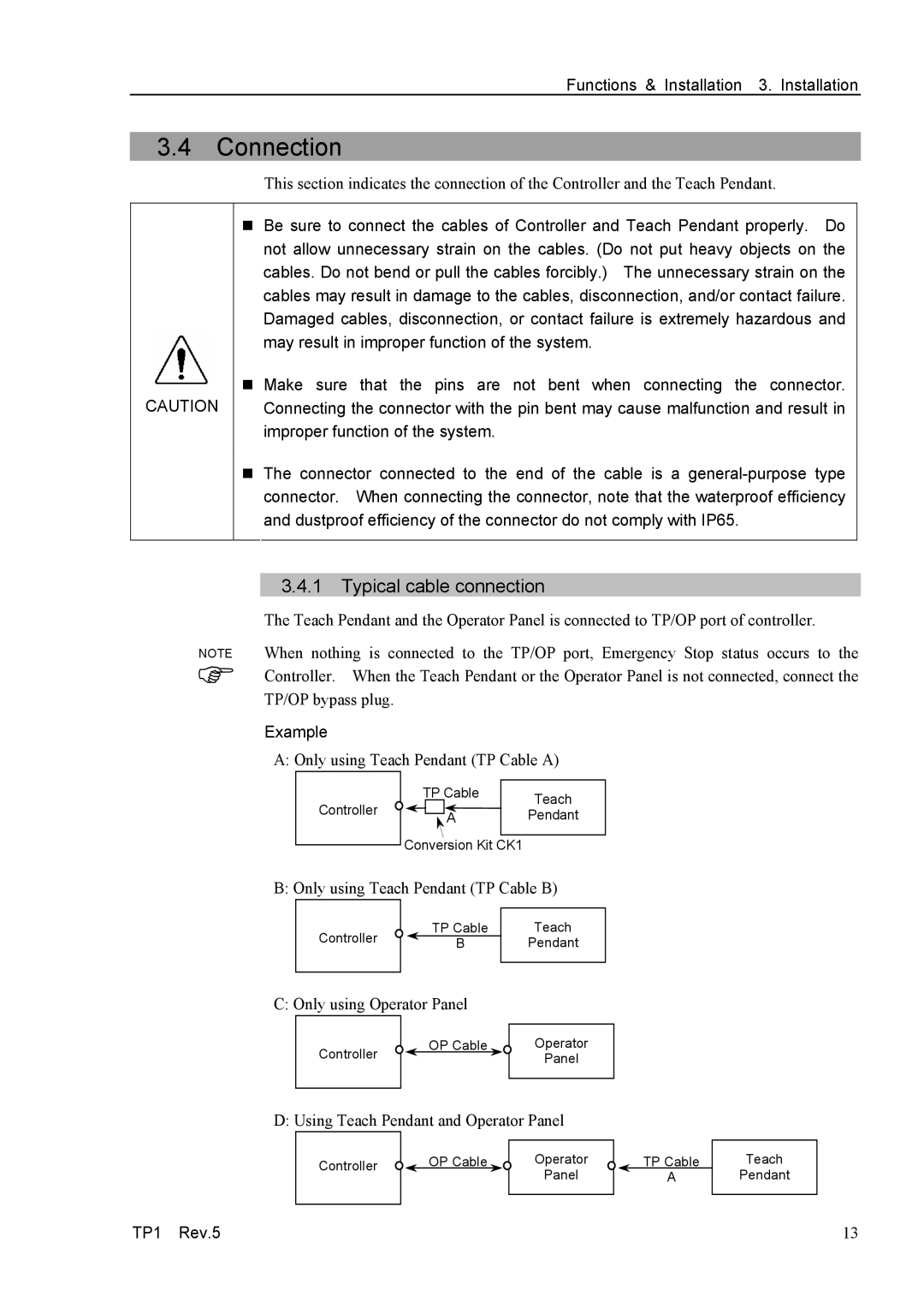
Example
A: Only using Teach Pendant (TP Cable A)
Controller
TP Cable | Teach |
| |
A | Pendant |
|
|
Conversion Kit CK1
B: Only using Teach Pendant (TP Cable B)
Controller
TP Cable
B
Teach
Pendant
C: Only using Operator Panel
Controller
OP Cable | Operator |
| Panel |
D: Using Teach Pendant and Operator Panel
Controller | OP Cable | Operator |
|
| Panel |
TP Cable
A
Teach
Pendant
TP1 Rev.5 | 13 |