Operation 2. TEACH Mode
(7) Press the <F2> key. The following screen appears.
(8)Remove the acrylic panel on the sensor monitor on the base connector plate.
 Acrylic Panel
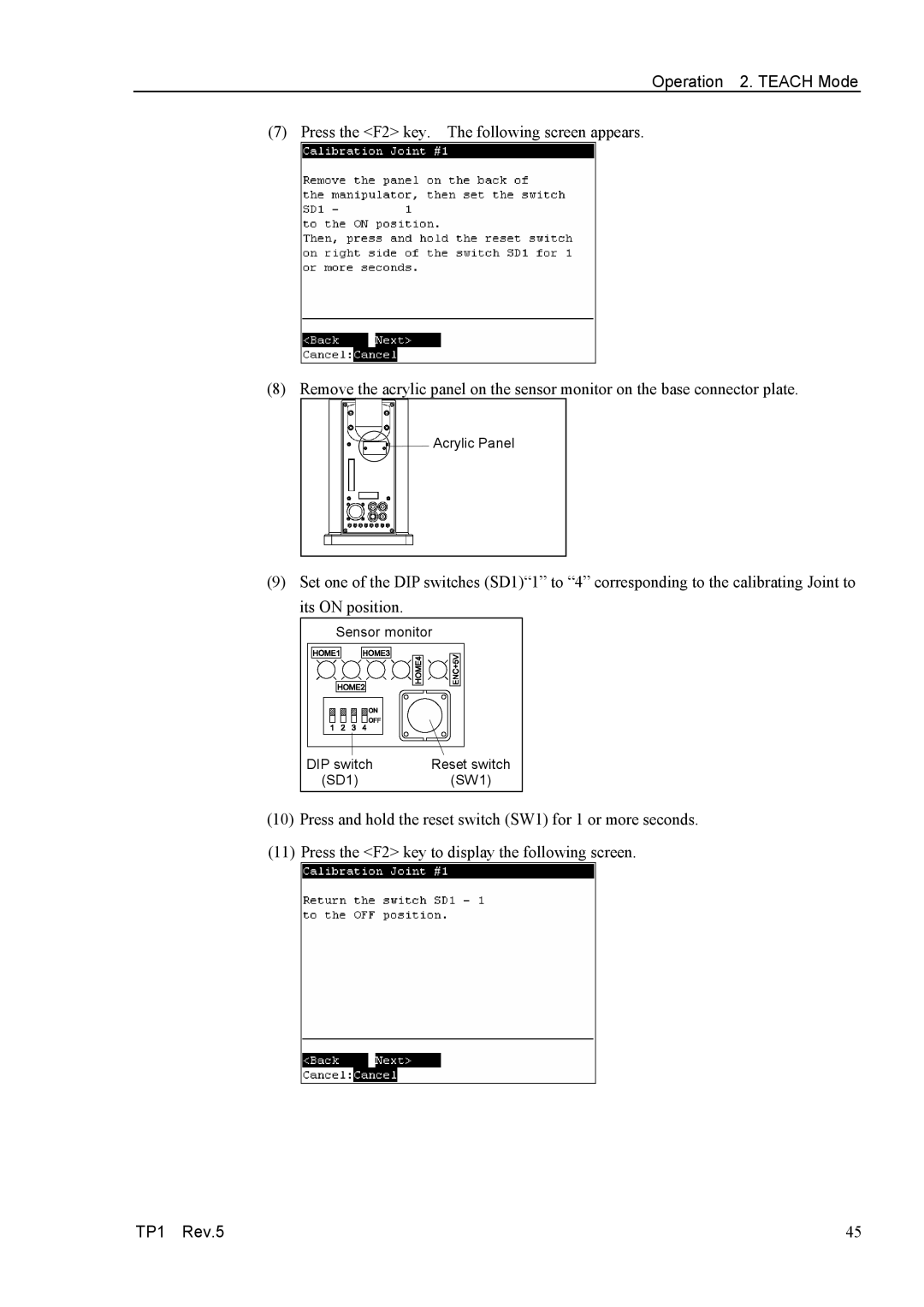
(9)Set one of the DIP switches (SD1)“1” to “4” corresponding to the calibrating Joint to
its ON position.
Sensor monitor
DIP switch | Reset switch |
(SD1) | (SW1) |
(10)Press and hold the reset switch (SW1) for 1 or more seconds.
(11)Press the <F2> key to display the following screen.
TP1 Rev.5 | 45 |