! Caution
There is a risk of fire
There is a risk of accident
Failure may result
Electric shock may occur
Accident may result
Electric shock may result
Never modify the product
Treat as industrial waste when disposing it
Electrical shock may result
Electric shock or injury may result
DCR
DCR FRNF50G11S-4UX
Use the following power supply to the inverter
Tightening torque and wire range
General instructions
Contents
Type Inverter type
Before Using This Product
Receiving Inspections
Appearance
1 Removing the surface cover for inverter of 30HP or less
Handling the Product Removing the surface cover
1 Storage environment
2 Output current reduction rate based on altitude
Installation and Connection
Installation Method
1 Operating environment
Voltage Inverter type Bracket screws Case mounting
Removing the ventilating covers
Electric shock or fire may result
Always connect a ground wire
Basic Connection Diagram Sink Logic
Basic Connection Diagram to PLC Sink Logic
Gfci
THR
1 Functions of main circuit terminals and ground terminals
Connecting the main circuit and ground terminals
Main circuit power terminals L1/R, L2/S, L3/T
Inverter output terminals U, V, W
DC link circuit terminals P + and N
Auxiliary control-power input terminals R0 and T0
DC reactor connecting terminals P1 and P +
Fire may result
Frequency Hz Power voltage range VAC
Inverter ground terminal
9 Fan power switching
Cnux U1 Cnrxtx L1/R-L3/T
FWD
Connecting the control terminals
13 Example of noise prevention
Others
Wiring of control circuit inverter of 40HP or more
Digital input terminals FWD, REV, X1 to X9 and CM
Transistor output terminals Y1 to Y4, CME
L3/T L1/R L2/S
Terminal arrangement
Main circuit terminals
L2/S L3/T Screw size M4
P24 DX − DX + 30A
Control circuit terminals
30C 30B
Y5C FWD REV
FRNF50G11S-4UX
Applicable equipment and wire size for main circuit
FRNF25G11S-2UX
FRNF50G11S-2UX
108
Phase
Power supply
Auxiliary power input Supplied Magnetic contactor
Trial Run
Operation
Inspection and Preparation before Operation
Operation Method
Appearance of Keypad Panel
Keypad Panel
Keypad panel operating system during normal operation
Alarm occurrence
Keypad Panel Operation System LCD screen, Level Structure
1 Overview of contents displayed for each level
Other than digital setting
Operating Keypad Panel Operation Mode
Setting digital frequency
Digital keypad panel settings F01=0 or C30=0
Menu screen
Switching the LED monitor
Setting function data
To switch to LED monitor display When power is turned on,
Display Reason for no modification Release method
To scroll Function Select screen rapidly , use alphabet
To move the screen in a unit grouped by
Screen
Checking function data
Monitoring operating status
PRG⇒PRG Menu F/D ⇒LED Shift
Data Setting 2.DATA Check 3.OPR Mntr ⇒4.I/O Check
8 I/O check
NRK=xxxxx NRR=xxxxx NRO=xxxxx
Maintenance information
Load rate measurement
EDC=
Alarm information
TRQ=
Maintenanc 6.LOAD Fctr 7.ALM INF ⇒8.ALM Cause
Alarm history and factors
Data copy
Data protection
Change disabled during operation
Memory error
Verify error
PRG⇒PRG Menu RESET⇒RESET
Alarm mode
Alarm detection order
Alarm detection order
Name
Function select Function select list FFundamental Functions
CControl Functions of Frequency
EExtension Terminal Functions
HHigh Performance Functions
PMotor Parameters
UUser Functions
AAlternative Motor Parameters
Function code
1 The factory setting value details
FRN001G11S-4UX FRN002G11S-4UX FRN003G11S-4UX
Function Explanation
C33
Frequency setting block diagram
F05 Rated voltage
Setting range 230 V series 80 to Series
F03 Maximum frequency
F04 Base frequency
F10 Electric thermal O/L relay Select F11 Level F12
F09 Torque boost
S T
F13 Electric thermal O/L relay for breaking resistor
U59
Accident may result
F14 Restart mode after momentary power failure
Power failure
F17Gain
Setting range Inactive
F15 Frequency limiter High F16 Low
F18Bias frequency
F26 Motor sound carrier frequency
Setting range 0.0 to 60.0Hz
Voltage adjust
Setting range 0 to 200%
F34
F36 30Ry operation mode
F33
Pulse rate
Set value
Accident may result F42 Torque vector control
P01, P09 2 T R Q
Off
Frequency selected
E01 X1 Terminal function E09 X9 Terminal function
Motor selected Related function
Motor
On →off
Set value Input signal Function Off →on
Disable PID control
Torque limit Related function F41 Value selected F40
H18
Alarm
Inverse operation when forward
F14 Off
E16 Torque limiter 2 driving E17 Torque limiter 2 braking
Settings when shipped from the factory
E10 Acceleration time E11 Deceleration time E12 E13 E14 E15
E20 Y1 terminal function E24
AL4 AL8
STG1 STG2 STG4
AL1
E30 FAR function signal Hysteresis
E25 Y5 Ry operation mode
Output current
E46Language
E45 LCD monitor function
Display item
Set value
C05 Multistep frequency C19
Setting range G11S 0.00 to 400.00Hz
C01 Jump frequency C02 C03 C04 Jump frequency Hysteresis
‹Setting example 100 F
Bias -100 to +100% GAIN0.0 to 200%
C30 Frequency command
Related functions E01 to E09 Set value11 F01
C31 Bias terminal12 C32Gain terminal12
T E R
C33 Analog setting signal filter
Tuning procedure
Inactive Active
P05 Motor 1 On-line Tuning
As injury may result
Set value Operation
Retry failed
Hen retry succeeded
FWD-CM
H08 Rev. phase sequence lock
H07 ACC/DEC (Mode select) pattern
Related functions U02 to U05
1 D E C M O D E
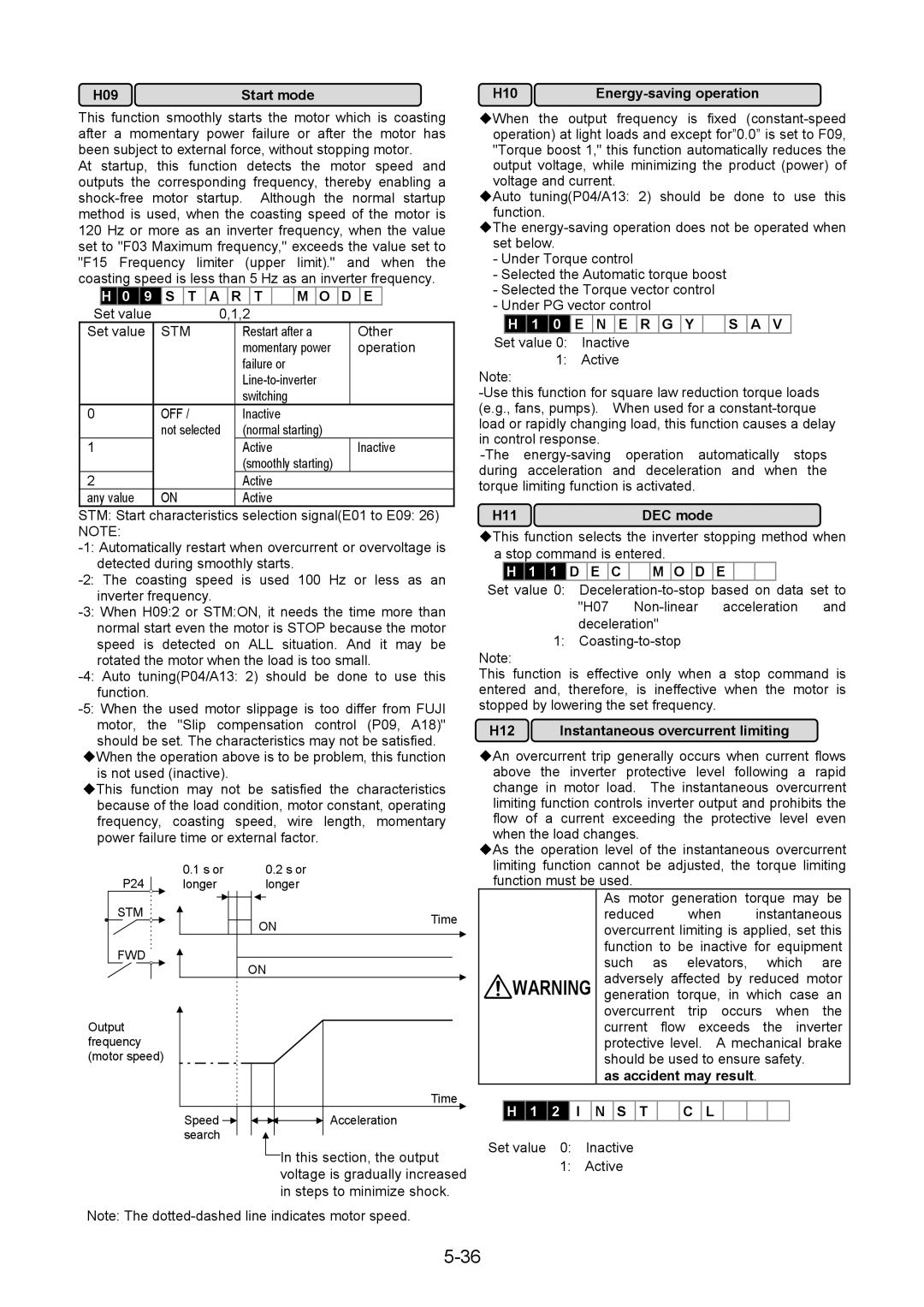
H09 Start mode
H11 DEC mode
H10 Energy-saving operation
Related functions
H13 Auto-restart Restart time H18 Torque control
To 5.0 seconds
‹This Function controls motor torque according to a
Set value Descriptions
H20 PID control Mode select H25 PID controlFeedback filter
H21 PID control Feedback signal
100% feedback amount
4 D G a I N
Deviation Time Operation amount
2 P G a I N
3 I G a I N
Value Inactive
Setting range 0.0 to 60.0 seconds
H26 PTC thermistor Mode select
H25 PID control Feedback filter
H39 RS-485 Response interval
Setting range 0 to Set value
H30 Serial link Function select
H31
Slippage = Synchronous speed-Rated speed
‹100% value of this function means maximum frequency fmax
Set value 15 becomes 1Hz. The set value 1 becomes 1/15Hz
U23
U15 Slip compensation filter time constant
Filter time constant of Slip compensation is set
U49 RS-485 protocol selection
U48 Input phase loss protection
U59 Braking resistor function select
Failure may result
Voltage detect gain adjustment
00 OH1 alarm at DC fan broken No alarm at DC fan broken
U61 Voltage detect offset and gain adjustment
Voltage detect offset adjustment
Motor overload memory retention
U89
List of Protective Operations
Protective Operation
Trip -2-1
Alarm Reset
Reset command
Keypad panel display Alarm display
Overcurrent
Trouble shooting
Ground fault
Protective function activation
Low voltage
Overvoltage
Overheating
Overtemperature inside air
Output wiring error
Memory error Er1
If motor does not rotate
Abnormal motor rotation
UP/DOWN
If the motor rotates but the speed does not change
If the motor generates abnormal heat
If the motor stalls during acceleration
Environment
Maintenance and Inspection
Check parts Check items How to inspect Evaluation Criteria
1 Periodical inspection list
Is there discoloration due to overheating?
Power is off Tighten
Use this function as follows
Estimate life
Page
Rectifier type
Digital Moving-iron Digital power Moving-coil
1 Meters for measuring main circuit
Meter Moving-iron
Inquiries about Products and Product Guarantee
Exclusion of Liability for Loss of Opportunity, etc
Free of Charge Warranty Period and Warranty Range
Service Contents
Applicable Scope of Service
Three-phase 230V series
Specifications
Standard Specifications
Three-phase 460V series
Transport 70 to 106 kPa
Common Specifications
Inch mm
Outline Dimensions
Outline Dimensions 30HP or less
460V Series
Outline Dimensions G11S 40HP to 350HP, P11S 40HP to 450HP
230V Series
W3 W4
Outline Dimensions G11S 400HP or more ,P11S 500HP or more
Fig図. C
Outline Dimensions Reactor Accessories for 100HP or more
Connection
Transmission Specification
Serial Interface Configuration
RS-485 Modbus RTU Serial Communications
Operation command data Registers
Inverter Function Code Access
Command and Monitor Data Registers
Frequency Setting Registers
Monitoring parameter registers
Bits binary data
Data Format Specification
Data format Index data ACC/DEC time, display coefficient
Data format Alarm Code
Data format Capacity code
Forward operation Current limiting
Inverter fault
Data format Pattern operation
All bit are on or active by
NAK
Data format Code setting 1-4 figures
Data format Type code
USA
Data format Auto tuning
Built-in Options
Options
10-1
FAB
Separately Installed Options Name Type Explanation
10-2
Motor
EMC product standard EN61800-3/1997 +A11/2000
Electromagnetic compatibility EMC
11-1
General
Filters
Recommended Installation Instructions
11-2
Applied Inverter Filter Type
11-3
Outline Dimensions RF3100-F11, RF3180-F11
Mccb
11-4
RCD or RFI filter Inverter
Harmonics restriction in Europe Union EU
11-5
2007-11 K07/K07 10CM


 M O D E