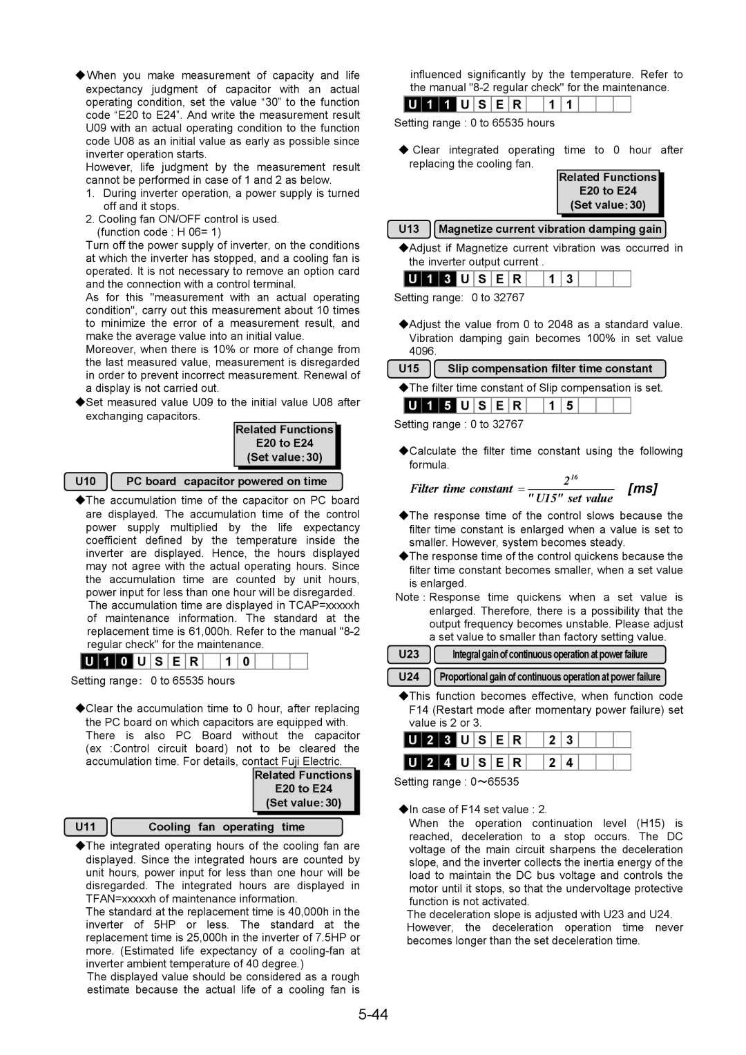
◆When you make measurement of capacity and life expectancy judgment of capacitor with an actual operating condition, set the value “30” to the function code “E20 to E24”. And write the measurement result U09 with an actual operating condition to the function code U08 as an initial value as early as possible since inverter operation starts.
However, life judgment by the measurement result cannot be performed in case of 1 and 2 as below.
1.During inverter operation, a power supply is turned off and it stops.
2.Cooling fan ON/OFF control is used.
(function code : H 06= 1)
Turn off the power supply of inverter, on the conditions at which the inverter has stopped, and a cooling fan is operated. It is not necessary to remove an option card and the connection with a control terminal.
As for this "measurement with an actual operating condition", carry out this measurement about 10 times to minimize the error of a measurement result, and make the average value into an initial value.
Moreover, when there is 10% or more of change from the last measured value, measurement is disregarded in order to prevent incorrect measurement. Renewal of a display is not carried out.
◆Set measured value U09 to the initial value U08 after exchanging capacitors.
Related Functions
E20 to E24
(Set value:30)
U10 PC board capacitor powered on time
◆The accumulation time of the capacitor on PC board are displayed. The accumulation time of the control power supply multiplied by the life expectancy coefficient defined by the temperature inside the inverter are displayed. Hence, the hours displayed may not agree with the actual operating hours. Since the accumulation time are counted by unit hours, power input for less than one hour will be disregarded. The accumulation time are displayed in TCAP=xxxxxh of maintenance information. The standard at the replacement time is 61,000h. Refer to the manual
U 1 0 U S E R | 1 | 0 |
Setting range: 0 to 65535 hours |
| |
◆Clear the accumulation time to 0 hour, after replacing the PC board on which capacitors are equipped with. There is also PC Board without the capacitor (ex :Control circuit board) not to be cleared the accumulation time. For details, contact Fuji Electric.
Related Functions
E20 to E24
(Set value:30)
U11 Cooling fan operating time
◆The integrated operating hours of the cooling fan are displayed. Since the integrated hours are counted by unit hours, power input for less than one hour will be disregarded. The integrated hours are displayed in TFAN=xxxxxh of maintenance information.
The standard at the replacement time is 40,000h in the inverter of 5HP or less. The standard at the replacement time is 25,000h in the inverter of 7.5HP or more. (Estimated life expectancy of a
The displayed value should be considered as a rough estimate because the actual life of a cooling fan is
influenced significantly by the temperature. Refer to the manual
U | 1 | 1 | U S E R | 1 | 1 |
Setting range : 0 to 65535 hours
◆Clear integrated operating time to 0 hour after replacing the cooling fan.
Related Functions
E20 to E24
(Set value:30)
U13 Magnetize current vibration damping gain
◆Adjust if Magnetize current vibration was occurred in the inverter output current .
![]() U
U ![]() 1
1 ![]() 3
3 ![]() U
U ![]() S
S ![]() E
E ![]() R
R ![]()
![]() 1
1 ![]() 3
3 ![]() Setting range: 0 to 32767
Setting range: 0 to 32767
◆Adjust the value from 0 to 2048 as a standard value. Vibration damping gain becomes 100% in set value 4096.
U15 Slip compensation filter time constant
◆The filter time constant of Slip compensation is set.
U 1 5 U S E R | 1 | 5 |
Setting range : 0 to 32767 |
|
|
◆Calculate the filter time constant using the following formula.
Filter time constant = | 216 | [ms] |
" U15" set value |
◆The response time of the control slows because the filter time constant is enlarged when a value is set to smaller. However, system becomes steady.
◆The response time of the control quickens because the filter time constant becomes smaller, when a set value is enlarged.
Note : Response time quickens when a set value is enlarged. Therefore, there is a possibility that the output frequency becomes unstable. Please adjust a set value to smaller than factory setting value.
U23 | Integral gain of continuous operation atpower failure |
U24 Proportional gain of continuous operation at power failure
◆This function becomes effective, when function code F14 (Restart mode after momentary power failure) set value is 2 or 3.
U | 2 | 3 | U | S | E | R | 2 | 3 |
U | 2 | 4 | U | S | E | R | 2 | 4 |
Setting range : 0~65535 |
|
| ||||||
◆In case of F14 set value : 2.
When the operation continuation level (H15) is reached, deceleration to a stop occurs. The DC voltage of the main circuit sharpens the deceleration slope, and the inverter collects the inertia energy of the load to maintain the DC bus voltage and controls the motor until it stops, so that the undervoltage protective function is not activated.
The deceleration slope is adjusted with U23 and U24. However, the deceleration operation time never becomes longer than the set deceleration time.
