Color Laserjet Enterprise CP4020/CP4520
Page
HP Color LaserJet Enterprise CP4020- CP4520 Series Printers
Trademark Credits
Copyright and License
Conventions used in this guide
Iv Conventions used in this guide
Table of contents
Removal and replacement
Print-quality test
119
Enww
Solve problems
265
383
Parts and diagrams
Appendix B Product specifications
Appendix a Service and support
Appendix C Regulatory information
515
Xvi
List of tables
17 Causes and solutions for fuser delivery delay jams 394
Table B-4
Enww
List of figures
49Paper-feeder pickup and feed operation
41 Remove the front-top cover 1 100
71 Remove the secondary transfer assembly 1 119
115 Remove the delivery assembly 3 146
161 Remove the tray-pickup drive assembly 1 178
209 Remove the fuser-drive assembly 1 212
19 Test the Tray 1 media-present sensor 261
20 Paper feeder external covers, panels, and doors 470
Xxx
Theory of operation
1Relationship between the main product systems
Basic operation
1Sequence of operation
Sequence of operation
Period Duration Description
2Engine-control system
Engine-control system
Solenoids
DC controller
Component abbreviation Component name
Clutches
Switches
Sensors
Sensors
Abbreviation Name Purpose Failure detection
Motors
Abbreviation Name Cooling area Type Speed
Fans
7High-voltage power supply circuits
High-voltage power supply
Circuit Description
Biases for each color
8Converted DC voltages
Low-voltage power supply
Sleep powersave mode
Safety
Low-voltage power supply failure
Overcurrent/overvoltage protection
9Fuser components
Fuser control
Type of component Abbreviation Name Function
Fuser sleeve temperature protection
Fuser temperature control
Failure detection
Fuser unit life detection
Fuser unit identification
8Laser/scanner system
Laser/scanner system
Laser/scanner failure
Protective-glass cleaners
9Protective-glass cleaners PGCs Theory of operation
ITB
Image-formation system
11Image-formation drive system
Functional block Steps Description
Image-formation process
Primary charging
Pre-exposure
Development
Laser-beam exposure
Secondary transfer
Primary transfer
Separation
Fusing
Drum cleaning
ITB cleaning
Print cartridge
23Print-cartridge system
Developing-roller engagement and disengagement
25 ITB unit
Intermediate transfer belt ITB unit
10Primary-transfer-roller engagement states
Primary-transfer-roller engagement and disengagement
SL1
Calibration
27ITB cleaning process
Image-stabilization control
Color-misregistration control
11Image-stabilization controls
29 Paper path
Pickup, feed, and delivery system
Component
Abbreviation Component
32Three main units of the pickup, feed, and delivery system
Cassette pickup
Pickup-and-feed unit
Cassette-presence detection
Top switch Center switch Bottom switch
Paper size
Cassette multiple-feed prevention
35Cassette lift mechanism
36Multiple-feed prevention
Multipurpose tray pickup
37Multipurpose tray pickup mechanism
Paper feed
38Paper-feed mechanism
Paper detection
Skew-feed prevention
14Print mode and feed speed
Fusing and delivery unit
Simplex printing
Duplex printing
40Fuser and delivery unit
Loop control
41Loop-control mechanism
42Pressure-roller pressurization control
Pressure-roller pressurization control
43Duplexing unit
Duplexing reverse and feed control
Duplex reverse and feed control
Duplex print operation
Enww
45Jam detection sensors
Jam detection
Jam Description
16Jams that the product detects
461 x 500 optional paper feeder
Optional paper feeder
473 x 500-sheet optional paper feeder
17Electrical components for the paper feeder
Motor control
Component Abbreviation Component name Type
Component Drives Failure detection
18Pickup feed components 1 x 500-sheet paper feeder
Paper-feeder pickup and feed operation
SW2 SW3 SW4
OFF
Paper-size detection and cassette-presence detection
SR2/SR8/SR9
Paper-feeder cassette lift operation
51Jam detection 1 x 500-sheet paper feeder
Paper feeder jam detection
52Jam detection 3 x 500-sheet paper feeder
Enww
Removal and replacement
Introduction
Removal and replacement strategy
Required tools
Electrostatic discharge
After performing service
Before performing service
Print-quality test
Post-service test
Parts removal order
2Parts removal order 1 Removal and replacement
3Parts removal order 2
Print cartridges
Customer self repair CSR components
5Remove the print cartridge 2
Toner-collection unit
7Remove the toner-collection unit 2 Removal and replacement
8Remove the toner-collection unit 3
ESD sensitive component
Formatter PCA
Remove the hard drive
Hard drive
Before proceeding, remove the following components
13Remove the hard drive 3 Removal and replacement
Remove the memory Dimm
Memory Dimm
Click Settings
Enable memory
Click the Device Settings tab
Next to Automatic Configuration , select Update Now
Installable Options area
Next to Automatic Configuration, select Update Now
Click the Installable Options menu
Windows
Tray
Fuser
Feed and separation rollers Trays
Pickup roller Tray
24Remove the pickup roller Tray 1 4 Removal and replacement
Enww
Secondary transfer roller
29Reinstall the transfer roller
Reinstall the transfer roller
Intermediate transfer belt ITB
32Remove the intermediate transfer belt 3
Enww
Identification and location
External panels, covers, and doors
35Remove the upper-left cover 1 Remove one screw
Upper-left cover
37Remove the upper-left cover 3
38Remove the power-supply cover Removal and replacement
Power-supply cover
Remove the left cover
Left cover
Remove the front-top cover
Front-top cover
43Remove the front-top cover 3
Remove the rear-top cover
Rear-top cover
Remove the right-front cover
Right-front cover
Reinstall the power button
Remove the control-panel assembly
Control-panel assembly
Enww
Remove the front-door assembly
Front-door assembly
53Remove the front-door assembly 2 Remove two screws callout
55Remove the front-door assembly 4
Remove the right-rear cover
Right-rear cover
58Remove the right-rear cover 2
Remove the rear cover
Rear cover
61Remove the right-door assembly 2
Right-door assembly
63Remove the right-door assembly 4 Removal and replacement
65Remove the right-door assembly 6
67Remove the right-door assembly 8 Removal and replacement
68Remove the right-door assembly 9
Cassette feed guide
Internal assemblies
72Remove the secondary transfer assembly 2
Secondary transfer assembly
Reinstall the secondary transfer assembly
Remove the separation pad Tray
Separation pad Tray
78Remove the separation pad 4 Removal and replacement
Enww
Remove the RD sensor assembly
Registration density RD sensor assembly
84Remove the RD sensor assembly 4
86Remove the RD sensor assembly 6 Removal and replacement
Carefully remove the assembly from the product
Registration assembly
89Remove the registration assembly 2
Remove the registration assembly
91Remove the registration assembly 4 Removal and replacement
93Remove the registration assembly 6
95Remove the registration assembly 8 Removal and replacement
Remove the residual-toner-feed motor
Residual-toner-feed motor
Remove the residual-toner duct and feed assembly
Residual-toner duct and feed assembly
99Remove the residual-toner duct and feed assembly 3
Enww
Remove the cartridge fan and environmental sensor
Cartridge fan and environmental sensor
Enww
Enww
Enww
Toner-collection sensor and scanner-thermistor assembly
Open the front-door assembly, and then remove one screw
Remove the delivery fan
Delivery fan
112Remove the delivery fan 2 Removal and replacement
Remove the delivery assembly
Delivery assembly
115Remove the delivery assembly 3 Removal and replacement
Remove two screws
118Remove the delivery assembly 6 Remove the assembly
121Reinstall the delivery assembly 2
Reinstall the delivery assembly
123Reinstall the delivery assembly 4 Removal and replacement
Remove the duplex-drive assembly
Duplex-drive assembly
Remove the power-supply fan
Power-supply fan
Remove the ICB
Interconnect board ICB
127Remove the ICB 2 Removal and replacement
Remove the DC controller PCA only
DC controller PCA only
Enww
Remove the low-voltage power supply
Low-voltage power supply Lvps
Enww
134Remove the low-voltage power supply 4
Enww
Remove the DC controller PCA and tray
DC controller PCA and tray
Remove two screws
Remove the high-voltage power supply lower
High-voltage power supply lower HVPS-D
Remove three screws
142Remove the high-voltage power supply lower 3
Release five tabs
Reinstall the high-voltage power supply lower
146Remove the high-voltage power supply lower 7
Remove the developing-disengagement motor
Developing-disengagement motor
Remove the exhaust fan and fan duct
Exhaust fan and fan duct
Enww
152Reinstall the exhaust fan and fan duct
Reinstall the exhaust fan and fan duct
Remove the pickup motor
Pickup motor
Remove the lifter-drive assembly
Lifter-drive assembly
Enww
Remove the lifter base assembly
Lifter base assembly
158Remove the lifter base assembly 2
Reinstall the lifter base assembly
160Reinstall the lifter base assembly 2
Remove the tray-pickup drive assembly
Tray-pickup drive assembly
163Remove the tray-pickup drive assembly 3
Remove the tray-pickup assembly
Tray-pickup assembly
Enww
168Remove the tray-pickup assembly 5 Removal and replacement
Enww
172Remove the tray-pickup assembly 9 Removal and replacement
173Remove the tray-pickup assembly 10
Laser/scanner assembly Y/M
176Remove the laser/scanner assembly Y/M 2
Remove the laser/scanner assembly Y/M
Enww
179Remove the laser/scanner assembly Y/M 5
Laser/scanner assembly C/Bk
181Remove the laser/scanner assembly C/Bk 2
Remove the laser/scanner assembly C/Bk
Enww
Reinstall the protective glass cleaner PGC actuators
184Remove the laser/scanner assembly C/Bk 5
187Reinstall the PGC actuators 3 Removal and replacement
189Reinstall the PGC actuators 5
Remove the high-voltage power supply upper
High-voltage power supply upper HVPS-T
191Remove the high-voltage power supply upper 2
Reinstall the high-voltage power supply upper
Remove the yellow, magenta, cyan, and black drum motors
Yellow, magenta, cyan, and black drum motors
Fuser motor
194Remove the fuser motor
Remove the fuser motor
Remove the ITB motor
ITB motor
Main-drive assembly
197Remove the main-drive assembly 2 Removal and replacement
Remove the main-drive assembly
198Remove the main-drive assembly 3 Remove 10 screws
Enww
203Reinstall the main-drive assembly 2
Reinstall the main-drive assembly
Enww
Enww
Enww
Fuser-drive assembly
Remove the fuser-drive assembly
212Remove the fuser-drive assembly 4
213Remove the fuser-drive assembly 5 Remove three screws
Reinstall the fuser-drive assembly
215Remove the fuser-drive assembly 7
Front door optional paper feeder
Enww
Rear cover optional paper feeder
220Remove the right-front cover optional paper feeder
Right-front cover optional paper feeder
Right door optional paper feeder
Enww
Remove the left cover optional paper feeder
Left cover optional paper feeder
Enww
Remove the right cover optional paper feeder
Right cover optional paper feeder
Remove the rear-right cover optional paper feeder
Rear-right cover optional paper feeder
Remove the pickup assembly optional paper feeder
Pickup assembly optional paper feeder
231Remove the pickup assembly optional paper feeder 3
Enww
Remove the lifter assembly optional paper feeder
Lifter assembly optional paper feeder
Remove the lifter-drive assembly optional paper feeder
Lifter-drive assembly optional paper feeder
Remove the pickup motor optional paper feeder assembly
Pickup motor assembly optional paper feeder
Remove the controller PCA optional paper feeder
Controller PCA optional paper feeder
Solve problems
Solve problems checklist
Solve problems checklist
Print a menu map
Menu map
Determine the problem source
Troubleshooting process
Pre-troubleshooting checklist
1Pre-troubleshooting checklist
Calibrate the product on
2Troubleshooting flowchart
Troubleshooting flowchart
Power on
Event log Information pages Image quality Interface
Power-on checks
Power subsystem
Power-on troubleshooting overview
Power-on timing approximate
Enww
Individual component diagnostics
Tools for troubleshooting
LED diagnostics
Understand lights on the formatter
Heartbeat LED
Engine diagnostics
Defeating interlocks
Engine-test button
Disable cartridge check
3Engine-test button
Paper-path test
Default state of bits
3Manual sensor diagnostic tests
Sensor or switch name Sensor or switch number
Manual sensor test special-mode test
TOP top of page sensor
C loop sensors
Fuser delivery sensor
Duplex re-pickup sensor
Output bin full sensor
Developer alienation
Fuser pressure-release sensor
Primary transfer-roller-disengagement sensor
Enww
16 Media sensor
Media sensor
Front-door switch
Right-door switch
Manual sensor test 2 special-mode test
5Manual sensor test 2 diagnostic tests
Test each switch individually Solve problems
Tray 1 paper present sensor
Tray 2 paper present sensor
Tray 2 paper surface 1 and 2 sensors
Tray 2 paper size switches
Tray 3 paper present sensor
Tray 3 paper size switches
Tray 3 feed sensor
Tray 3 paper surface 1 and 2 sensors
Tray 5 paper size switches
Tray 4 paper size switches
Tray 5 paper present sensor
Tray 5 feed sensor
Enww
Defeating
Enww
Enww
25Test the new ITB sensor
New ITB sensor
26Test the right door switch Solve problems
Tray 3, 4, and 5 right door switch
Paper-path sensors test
7Paper-path sensors diagnostic tests
Print/stop test
Sensor name Sensor number
Component test special-mode test
Component tests
8Component test details
Fuser Motor
Yellow Laser Scanner
Fuser Pressure Release Motor
Alienation Motor
Repeat
Duplex Refeed Clutch Solenoid
Block diagrams
Diagrams
28Optional paper feeder 1 x 500-sheet
29Optional paper feeder 3 x 500-sheet
9Formatter PCA
Plug/jack locations
DC controller connector locations
Location of connectors
10DC controller connectors
11Controller PCA connectors
32Controller PCA connectors
33External component locations
Locations of major components
34Major component locations 1
35Major component locations 2
36Major component locations 3
Ite Description
11 9
38PCA component locations
39Optional paper feeder 1 x 500-sheet component locations 1
40Optional paper feeder 1 x 500-sheet component locations 2
41Optional paper feeder 3 x 500-sheet component locations 1
42Optional paper feeder 3 x 500-sheet component locations 2
Timing chart
General timing chart
General circuit diagram 1
Circuit diagrams
Control
Paper feeder circuit diagram 1 X 500-sheet
Paper feeder circuit diagram 3 X 500-sheet
Open the HP Easy Printer Care software
HP Easy Printer Care
HP Easy Printer Care software sections
Section Options Support tab
Settings tab
HP Proactive Support
Overview and Support tabs
Color Access Control
Section Options Alert Settings link
Internal print-quality test pages
Print-quality-troubleshooting pages
Yellow Green
51Black print-quality troubleshooting
Diagnostics
Diagnostics
Create and use the cleaning
Cleaning
Configuration
Configuration
Memory Event log Security Paper trays and options
HP embedded Jetdirect
Security Settings information
54 Embedded protocol
Embedded protocol
12Important information on the configuration pages
Finding important information on the configuration pages
Color-band test
Repetitive defects ruler
Print-quality troubleshooting tools
Calibrate the product
Control panel menus
Control panel menus
Show Me How menu
Retrieve job menu
Enww
ALL Jobs no PIN Print
When Print or Print and Delete is
Hold jobs, Print and Delete is
Delete
Paper handling menu
Information menu
Manage supplies menu
Continue
Color Cartridges Stop
Print in Black
Transfer KIT Stop
Magenta Cartridge
User Defined LOW Yellow Cartridge
Cyan Cartridge
Black Cartridge Transfer KIT
Printing menu
Configure device menu
Default Custom Paper Unit of Measure
Default Paper Size
Size Dimension
Print PS Errors OFF
PCL sub-menu
Print Quality menu
X1 Shift
Mode Expanded
Y1 Shift
X2 Shift
Print Mode
Adjust Paper
Restore Optimize
NOW Delay
Cleaning
Auto Cleaning OFF
Auto Cleaning Letter
Edge Control OFF
Create
Select the Create Cleaning
Process
System setup menu
Disabled
PS Defer Media Enabled
USE Requested Tray Exclusively
First
Letterhead Mode OFF
USE Another Tray Enabled
Sleep Delay Minute
Alternative
Custom
Wake Time
Optimum SPEED/ENERGY Faster First
Usage Save Energy
Auto Continue OFF
JAM Recovery Auto
RAM Disk Auto
Language
13Embedded Jetdirect menu
Menu
Settings Subnet Mask
IPV4 Settings Config Method Bootp
Default
Default IP Auto IP
Settings
IPV6 Settings Enable
Dhcp Renew
Primary DNS
IPX/SPX Enable
Idle Timeout
Appletalk Enable
OFF DLC/LLC Enable
Reset
Disable
Reset Security YES
Diagnostics Embedded Tests
Data Path Test YES
Snmp Test YES
Select ALL YES
Tests
Ping Results
Print Results YES
Packets Sent
Packets
Link Speed Auto 10T Half 10T Full 100TX Half 100TX Full
Refresh YES
Diagnostics menu
Resets menu
Paper Path Test
Paper Path Sensors
Source ALL Trays
Tray
Product PINs
Service menu
Voltage power supply
Color Band Test Print Test
Control-panel message types
Interpret control-panel messages
Control-panel messages
XX values
13.XX.YY Fuser Wrap JAM
13.XX.YY Fuser Area JAM
13.XX.YY JAM Above TOP Output BIN
13.XX.YY JAM in Lower Right Door
Embedded I/O Buffer Overflow
Transfer Unit Error
Parallel I/O Buffer Overflow
Parallel Serial Buffer
Fuser Error
Xxxx Error
To continue turn off then on
See Fuser on
XX Error
XY Error
55.XX.YY DC Controller Error
See DC controller PCA and tray
Error
Description Recommended action Error
BO Cleaning Motor Error
59.A0 Error
59.C0 Error
Replace Toner Collection Unit
59.F0 Error
No System
Values
Permanent Storage Full
8X.YYYY EIO Error
Storage Error Settings
8X.YYYY Embedded Jetdirect Error
Changed
Black Cartridge LOW
Calibration Reset Pending
Black Cartridge LOW Less than Xxxx Pages
Black Cartridge Very LOW
Card Slot Device Failure
Cleaning Disk X% Complete
Card Slot File Operation Failed
Card Slot File System is Full
Close Lower Right Door
Cleaning Cyan Cartridge LOW
Close Right Door
Collection Unit Almost Full
Data Received
Cyan Cartridge Very LOW
DATE/TIME = YYYY/MMMM/DD Hhmm
EIO X Disk Initializing
EIO is Write Protected
HP Secure Drive Disabled
EIO not Initialized
Expected Drive Missing
Install Fuser
Install Color Cartridge
Install Supplies
Install Transfer Unit
Media insert required in tray
Magenta Cartridge LOW
Loading Program
Magenta Cartridge LOW Less than Xxxx Pages
Magenta Cartridge Very LOW
Moving Solenoid
NON HP Supply Installed
Moving Solenoid and Motor
Printing Stopped
RAM Disk File Operation Failed
RAM Disk Device Failure
RAM Disk File System is Full
RAM Disk is Write Protected
Remove Shipping Sheet
Replace Supplies Using black only
Replace Color Cartridge
Replace Fuser KIT
ROM Disk Device Failure
Replace Transfer KIT
ROM Disk File System is Full
ROM Disk File Operation Failed
ROM Disk is Write Protected
Sanitizing Disk X% Complete
Manage Supplies menu on
Supplies LOW
Printing Black only
Supplies Very LOW
Toner Collection Unit Very LOW
Toner Collection Unit LOW
Transfer KIT LOW
Transfer KIT LOW Less than Xxxx Pages
Tray X Empty Type Size
Tray X Type Size
Tray X Open
Tray X Overfilled
Unsupported Supply Installed
Unsupported Drive Installed
USB Accessory Error
USB Accessory not Functional
Waiting for Tray X to Lift
Wait for Printer to Reinitialize
Warming UP
Yellow Cartridge LOW
Yellow Cartridge Very LOW To continue press OK
Yellow Cartridge Very LOW
Print an event log
Event log messages
Show an event log
Clear the event log
Sample event log
Event log message Description Comments
Event log message table
Quick Calibrate NOW,
Configure DEVICE, and then
Then press theOK button
DC controller Nvrm is not
Reading the header number and size 99.00.08
Common causes of jams
Clear paper jams
Product is jammed
ITB
Jam code
15Common causes of jams by area
Jam locations
Type of jam Procedure
13.XX.YY JAM in Optional Trays
Clear jams in the right door
Enww
Enww
Clear jams in Tray
Clear jams in the output bin area
Enww
Clear jams in Tray 2 or optional Trays 3, 4, or
Clear jams in the lower right door Tray 3, 4, or
Jams in the output bin
Jam causes and solutions
Jams in the fuser and transfer area
19Causes and solutions for fuser delivery stationary jams
21Causes and solutions for pickup delay jams
20Causes and solutions for residual media jams
23Causes and solutions for duplexing reverse jams
22Causes and solutions for pickup stationary jams
24Causes and solutions for duplex repick jams
Right-door assembly on
25Causes and solutions for residual media jams
Jams in Tray 1, Tray 2 and internal paper path
26Causes and solutions for pickup delay jam 1 tray pickup
Jams in Tray 3, 4,
27Causes and solutions for pickup stationary jams
29Causes and solutions for residual media jams
Set the jam recovery feature
Change jam recovery
Product feeds multiple sheets
Solve paper-handling problems
Product feeds incorrect page size
Product pulls from incorrect tray
Paper does not feed from Tray 2, 3, 4, or
Paper does not feed automatically
Paper does not feed automatically
Paper does not feed from Tray 2, 3, 4, or
Envelopes jam or will not feed in the product
Transparencies or glossy paper will not feed
Transparencies or glossy paper will not feed
Envelopes jam or will not feed in the product
Product will not duplex or duplexes incorrectly
Output is curled or wrinkled
Output is curled or wrinkled
Automatic Configuration list
Under Installable Options, click Update Now
Properties or Printing Preferences
PRE-ROTATION Mode
30MP modes under the Adjust Paper Types sub menu
Use manual print modes
31MP modes under the Optimize submenu
Problem Sample Cause Solution
Solve image-quality problems
Image defects table
Transfer belt ITB on
Assembly Y/M on page 186 or
Power supply lower HVPS-D
Assembly. See Secondary transfer
Execute a Pressure roller clean
Clean the paper path
Clean the product
Clean the product
Problem Cause Solution
Solve performance problems
Solve direct-connect problems
Solve connectivity problems
Solve network problems
Solve connectivity problems
Service menu
Service mode functions
Refurbish Cycle Count
Refurbish page Count
Serial Number
Cold Reset Paper
Service ID
NEW Registration Roller
Media Sensor Value
Restore factory-set defaults
Product resets
Hard disk initialization optional
Nvram initialization
Product cold reset
Product updates
Parts and diagrams
Order parts, accessories, and supplies
Part numbers
Accessories
Print cartridges and toner collection unit
Memory
1Maintenance kits
Service maintenance kits
Customer self repair CSR parts
2110V and 220V unique components
Unique components
3Simplex and duplex unique components
4Common fasteners
Screws
How to use the parts lists and diagrams
1External covers, panels, and doors
External covers, panels, and doors
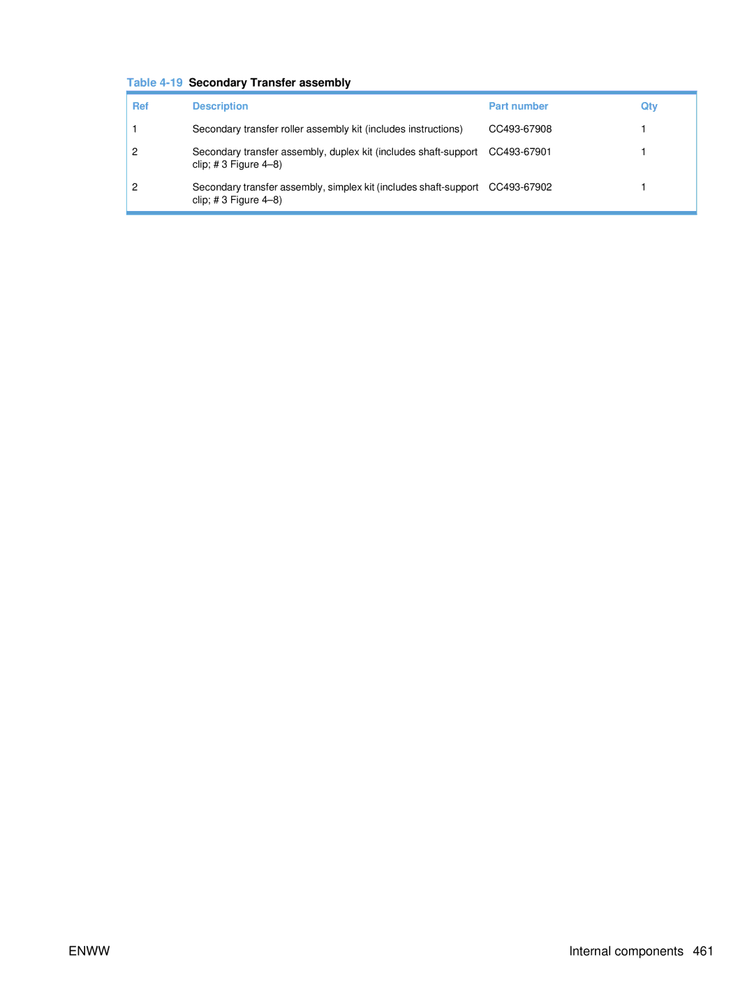
Description Part number Qty
5External covers, panels, and doors
2Right door assembly
Right door assembly
6Right door assembly
Front door assembly
7Front door assembly
Internal components 1
Internal components
8Internal components 1
Internal components 2
9Internal components 2
6Internal components 3
Internal components 3
10Internal components 3
Internal components 4
11Internal components 4
8Internal components 5
Internal components 5
12Internal components 5
Simplex Model Duplex Model
Internal components 6
13Internal components 6
10Internal components 7
Internal components 7
14Internal components 7
Cassettes
Cassettes
15 Cassette
Paper pickup assembly
16Paper pickup assembly
13Tray 1 paper pickup assembly
Tray 1 paper pickup assembly
17Tray 1 paper pickup assembly
Simplex Model Duplex Model
18Registration assembly
15Secondary transfer assembly
19Secondary Transfer assembly
16Delivery assembly
20Delivery assembly
Fuser assembly
Fuser assembly
21Fuser assembly
18 PCAs
PCAs
22 PCAs
Paper feeders
Assessories
Paper feeders
23Paper feeders
1x500 3x500
Paper feeder external covers, panels, and doors
24Paper feeder external covers, panels, and doors
500 paper feeder main body
500 paper feeder main body
251 X 500 paper feeder main body
223 X 500 paper feeder main body
263 X 500 paper feeder main body
27Alphabetical parts list
Alphabetical parts list
Alphabetical parts list
Delivery assembly
Fuser drive assembly, simplex RM1-6702-000CN
Paper pickup assembly
Tray 1 paper pickup assembly
Shutter arm assembly RM1-5585-000CN
Upper main cable assembly RM1-5800-000CN
28Numerical parts list
Numerical parts list
RC2-4218-000CN Tray, waste toner catch
Enww
RK2-2604-000CN Flat flexible cable DCC to Hvps lower
RM1-5520-000CN Cover, inner
RM1-5781-000CN High voltage power supply, upper
Enww
WC2-5637-000CN Switch, push
Enww
Service and support
Hewlett-Packard limited warranty statement
Page
HP Color LaserJet Fuser Kit Limited Warranty Statement
Transfer
End User License Agreement
Enww
Customer self-repair warranty service
Customer support
Product specifications
Performance specifications
Physical specifications
Electrical specifications
Table B-1Product dimensions
Environmental specifications
Acoustic specifications
Table B-3Power requirements
Table B-4Power consumption average, in watts1246
Table B-6Media registration and image placement accuracy
Skew specifications
Regulatory information
FCC regulations
Environmental product stewardship program
Paper
Return and recycling instructions
United States and Puerto Rico
Non-U.S. returns
Chemical substances
Material restrictions
HP Color LaserJet Enterprise CP4020-CP4520 Series
Material Safety Data Sheet Msds For more information
Declaration of Conformity
Laser safety
Safety statements
Vcci statement Japan Power cord instructions
Power cord statement Japan
Varoitus
GS statement Germany
Cabinet/stand
Symbols/Numerics
Dhcp
See also jams
Nvram
See also counts
Enww
Recycling
Enww
See also cassette
Enww
Page
CC489-90936* *CC489-90936