Windows 2000 1. On the client computer, go to Start→Settings→Control Panel and
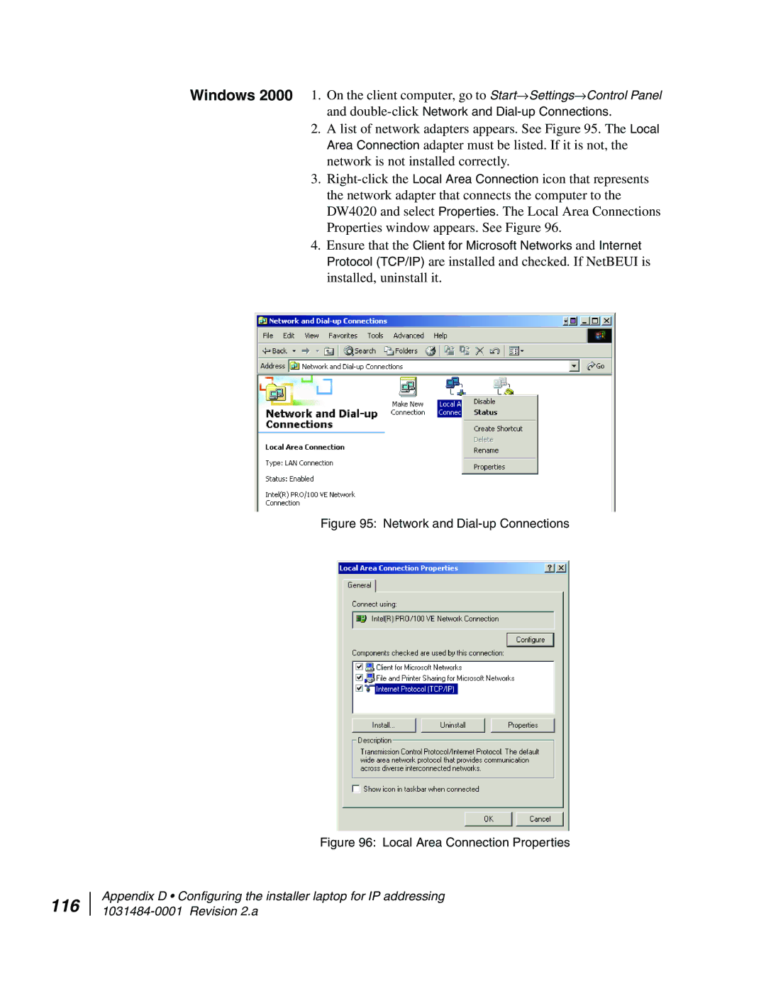
2.A list of network adapters appears. See Figure 95. The Local Area Connection adapter must be listed. If it is not, the network is not installed correctly.
3.
4.Ensure that the Client for Microsoft Networks and Internet Protocol (TCP/IP) are installed and checked. If NetBEUI is installed, uninstall it.
Figure 95: Network and Dial-up Connections
Figure 96: Local Area Connection Properties
116
Appendix D • Configuring the installer laptop for IP addressing