Manuals
/
Hughes
/
Computer Equipment
/
Network Hardware
Hughes
DW4020
manual
Component stack
Models:
DW4020
1
27
136
136
Download
136 pages
42.39 Kb
24
25
26
27
28
29
30
31
Characteristic DW4020
Install
Detecting a signal or is not
System Status indicator
Configuring Boot Parameters
System Status reports Problem
Gateway reset
Websetup Detection
Final assembly
Firewall Settings
Page 27
Image 27
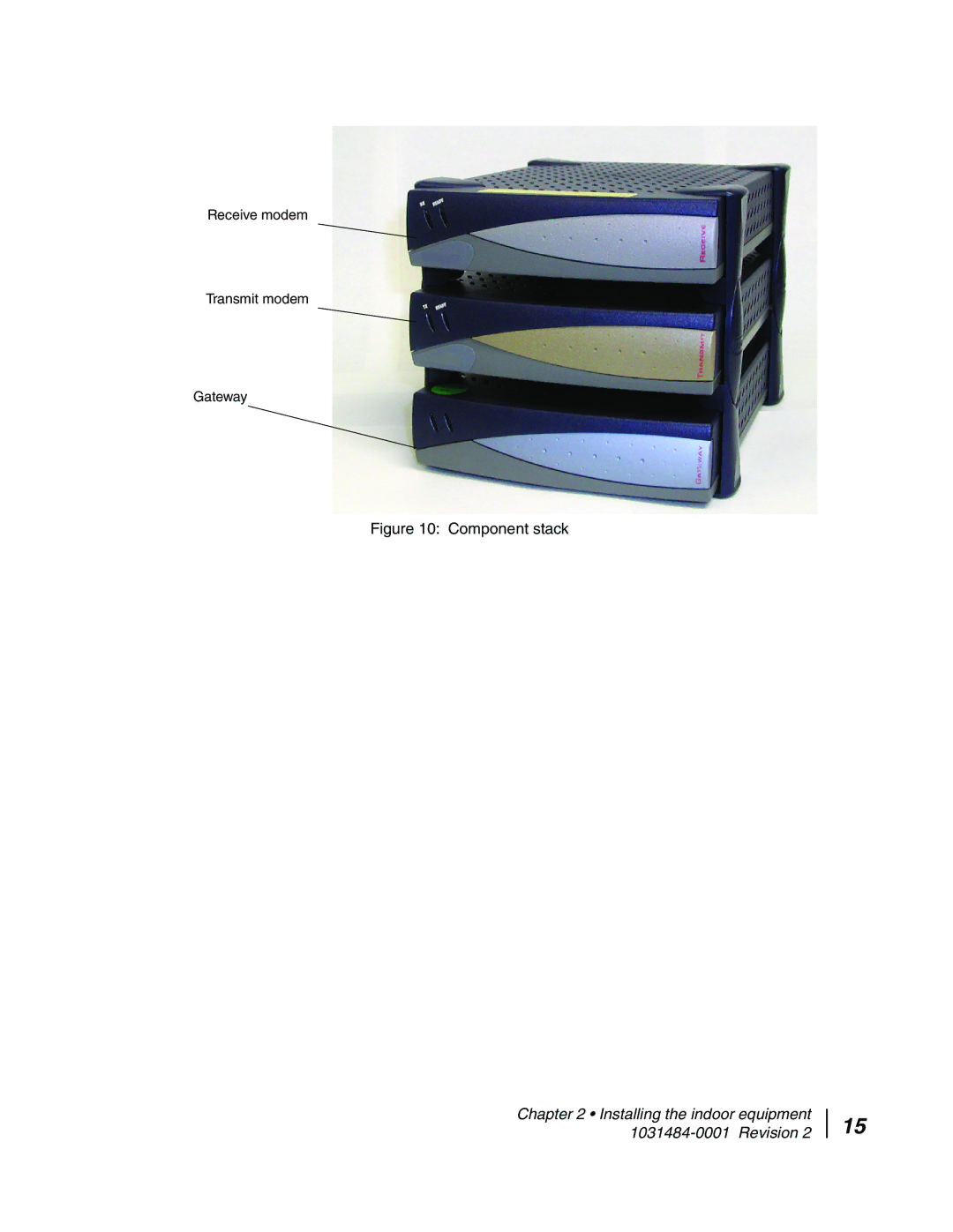
Receive modem
Transmit modem
Gateway
Figure 10: Component stack
Chapter 2 • Installing the indoor equipment
1031484-0001
Revision 2
15
Page 26
Page 28
Page 27
Image 27
Page 26
Page 28
Contents
DW4020 Installation Guide
Trademarks
Declaration of Conformity
Iii
Revision
Contents
Chapter User Interface
Appendix B Internet and the DW4020
Vii
Viii
Types of warnings used in this manual
Important safety information
Important safety information 1031484-0001 Revision
Audience profile
Organization and updates
About this document
Scope and audience
Xii
Conventions Related publications Revision record
DW4020 purpose and components
Introduction
Inroute
Characteristics and identification of equipment
Characteristic DW4020
Important notes
Customer installation requirements
Installing the indoor equipment
Two DW4020 installation methods
Summary of DW4020 installation process
Prohibited area
Installing the indoor equipment 1031484-0001 Revision
Installation screen
Device Installation Status
Installing the system using a modem
ADP-64AB B
Assembling the components, modem installation method
Mount the components on two clips
Component stack
Connect the component interconnection cables. See
Connect Ethernet, power up, and read the Gateway LED display
Status LED Ready LED
Obtain IP address and test Ethernet connection
Basic Receive and Transmit Modem LED States
Ethernet port LEDs
Select Start→Programs→Direcway Installer→Websetup.
Websetup Detection
Registration Connection Authentication
Service Offerings
Enter ZIP code
Antenna Pointing Receiver
Verify the ZIP code matches the antenna location and select
Post-commissioning
Start manual cross-pol pass and peak isolation
Manual cross-pol passed select Stop Test
ACP passes select Exit
Connect to customer computer and confirm surfing
Final cabling
Installing the indoor equipment 1031484-0001 Revision
User Interface
User Interface Home screen
How to access the User Interface
Home screen
System Status reports Problem
System Status screen
System Status indicator
On-line help for status messages
Transmit status TxCode messages and corrective actions
Detecting a signal or is not
Performing the Connectivity Test
DW4020 connections
Receive code RxCode messages and corrective actions
Receive Statistics
Receive Statistics screen
Transmit Statistics
Transmit Statistics screen
System Information
System Information print and save this screen
Network Operations Center NOC Connectivity
Connectivity Test Menu
Connectivity Test
Firewall Menu
Firewall Settings
Port numbers and protocols
Help Menu
MyDIRECWAY
Software updates and the User Interface
DW4020 LEDs
DW4020 LEDs and troubleshooting
Normal operation, no transmit or receive
DW4020 LEDs status
Normal operation, data being sent and received
Problem receive modem Ready LED not on
Receive modem Ready LED not lit
Transmit modem Ready LED not lit
Gateway LEDs not lit
Gateway Status LED blinks amber
Gateway LEDs flash, receive modem Ready LED off or flashing
Ready LED
LED blinking indicating status codes
Receive modem Ready LED blink patterns
Ethernet port LEDs
Glossary
Glossary
Glossary Revision
Glossary
Abbreviation Term Or Acronym
Abbreviations and Acronyms
Abbreviations and Acronyms 1031484-0001 Revision
Lat/Long Decimals to Minutes Table
Right Minutes Decimal
Internet protocol IP and transmission control protocol TCP
Internet and the DW4020
IP addressing and the DW4020
Category Lowest address Highest address Example or comment
Appendix B The Internet and the DW4020 1031484-0001 Revision
Private IP addressing and DW4020 customers
DW4020s provide connections
Items needed for installation
Installing the DW4020 Manually
PN 1031105-0001 and ADP-64AB B above bar code
Assembling the components
Mount the components on two clips
Component stack
Attach coaxial cables
Attach network cables
Final assembly
Powering up and reading the DW4020 LED display
DW4020 LEDs
DW4020 LEDs status
Normal operation, data being sent and received
Receive modem Ready LED not lit
Transmit modem Ready LED not lit
Gateway LEDs not lit
Gateway LEDs flash, receive modem Ready LED off or flashing
Blinking. The blink patterns are described below for your
Ethernet port LEDs
Communicating with the Gateway through the serial port
Configuring Hyperterminal or terminal emulation program
Select Start→Accessories→Hyperterminal and click on
Connect To window
COM1 Properties window and pull-down menus
Press Enter to display the Main Menu shown in Figure
100
101
Configuring Boot Parameters
102
Display Current Configuration Screen
103
104
Installation Menu
105
106
Display Main Statistics
107
Verifying software download
108
109
Gateway reset
110
DW4020 status information via the serial port
Addrclosed
111
112
Other options
113
Configuring the installer laptop for IP addressing
Network window
114
TCP/IP Properties
115
Network and Dial-up Connections
116
Internet Protocol Properties
117
Network Connections
118
119
120
121
Installation checklist
122
123
Index
124
Top
Page
Image
Contents