Novajet
Printing history
FCC Statement U.S.A
For NovaJet 736 and 750 FCC Statement U.S.A
VDE Statement
Material Safety Data Sheet
Warranty or Damage Claims
Table of Contents
Troubleshooting
Assembly\Disassembly
Parts List
List of Illustrations
Troubleshooting
Xvi
List of Tables
This Page Intentionally Left Blank Xviii
NovaJet 500/630/700 Series Inkjet Printers
Introduction
General Description
Electrostatic Discharge ESD Sensitivity
Overview
Followed by a paragraph describing the concern Indicated by
Printer Specifications
Dimensions
Environment Weight
General Description
Technical Support
Help Desk Telephone
Help Desk FAX
Theory of Operation
General Block Diagram
Paper Media Axis Drive
Carriage Axis Drive
Media Feed and Take-Up System
Main Printed Wiring Assembly Mpwa
Gate Array
Microprocessor
Flash Eeprom
Memory Circuits
Dram
Stepper Motor Controller
Serial Eeprom
Theory of Operation
Servo Motor Controller
Detector Encoder Strip Output of Detector
10. Interface Circuits
Interface Circuits Serial & Parallel
Carriage Assembly Circuits
Control Panel
Power Supply
Theory of Operation
Scheduled Maintenance
Maintenance3
Cleaning Procedures
External Cleaning
Service Station Cleaning
Slide Shaft Cleaning
Linear Encoder Strip Cleaning
Encoder Strip Cleaning
Cartridge Jet Area & Dimples Cleaning
Flex Cable Contacts
Flex Cable Contact Cleaning
Clean and Inspect Mpwa
Clean and Inspect Stepper Motor Gears
Reseat Connectors on Mpwa and Carriage Board
Clean and Inspect Carriage Assembly
Main PWA Connection Locations Main PWA Connections
Carriage PWA Connection Locations Carriage PWA Connections
Replace Carriage Bushings
Ribbon Connector Locking Mechanism
Servo Motor
Servo Motor Winding Resistance Check
Stepper Motor
Stepper Motor Winding Resistance Check
Power Feed and Take-Up Motor
Power Feed and Take-Up Motor Winding Resistance Check
10. Examples of Banding
Banding Hardware vs Software
Common Banding Causes
Maintenance
Slide Shaft Profile Adjustment
Alignments/Adjustments
11. Dial Gauge Micrometer Assembly
12. Measurement Positions for Slide Shaft
13. Slide Shaft Profile Adjustment
14. Carriage Head Height Tolerance
Head Height Alignment Procedure
Zero Ensure Pressure is Placed on the Rear Gauge Cartridge
18. Support Bracket Placement
Maintenance
19. Color Calibration
Color Calibration
20. Utility Menu
21. Color Calib Menu
23. Slow Deadband
Deadband Alignments
24. Service Menu
25. Calibration Deadband Menu 500 Series
Deadband Alignment for 500 Series
27. Calibration Menu
Color Deadband Alignment for 630/700 Series
28. Color Db Menu
Paper Axis Calibration
29. Paper Axis Test
30. Diagnostics Menu
Diagnostics Menu
Maintenance
Maintenance
32. Nvram Clear and Clock Reset Menu
Limited Access Menu
Firmware Download/Upgrading for the PC
Then type Print /DLPT1 A\XXXX.ROM and press Enter
Firmware Download/Upgrading for the MAC
Maintenance
Internal Cabling and Signal Flow Diagrams
33. Mpwa Connections Diagram
34. Carriage PWA Connections Diagram
35. Leg Harness Connections Diagram
36. Leg Harness Connections Diagram
No Power
Troubleshooting4
Media Does Not Move
Initialization Failure
Internal Error Carriage Axis Failure
Troubleshooting Table
Internal Error Paper Sensor Failure
Internal Error Encoder Sensor Failure
Internal Error Auto-Sensor Failure
Internal Error Mpcb Failure
Unrecognized Cartridges Error
Image Skews or Moves
Does Not Print
Ink Cartridge Misfiring
Troubleshooting Table
Printer Output is Banding Horizontal
Paper Skewing
Nvram
Printer Output is Banding Vertical
Printer Output is Banding Horizontally and Vertically
Keypad Locked- Up or Not Func- tioning Properly
Noisy Operation
Line Quality Degraded
Media Take-Up Motor Not Operating Sensor Works
Fan Does Not Power Up
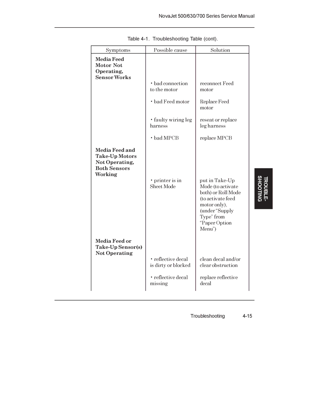
Media Feed or Take-Up Sensors Not Operating
Media Feed Motor Not Operating Sensor Works
Troubleshooting Table
TROUBLE- Shooting
Initialization Troubleshooting 500 Series
LED D2
Initialization Troubleshooting 630/700 Series
Carriage Board LED D2 and D5 Locations
This Page Intentionally Left Blank
Assembly\Disassembly5
Remove the Left, Top, and Right Covers
Right Cover Assembly Removal/Installation
Left Cover Assembly Removal/Installation
Left Cover Removal/Installation NovaJet
Install the Left, Top, and Right Covers
Remove the Keypad and Display
Keypad and Display Installation/Removal
Keypad and Display Grounding Connections
Install the Keypad, Display, and Display Power Converter
Remove Extra Memory Simm
Extra Memory Simm Installation/Removal
Remove the Mpcb Main Printed Circuit Board
Install Extra Memory Simm
Assembly\Disassembly
Mpcb Removal
Install the Mpcb
Remove Power Supply, Cooling Fan, and AC Entry Module
Power Supply Removal
Cooling Fan/AC Entry Module Removal
Install the Power Supply, Cooling Fan, and AC Entry Module
Remove Servo Motor
10. Slacken Carriage Belt
Install Servo Motor
Remove the Ink Delivery System
11. Chain Support Bracket Removal
Install the Ink Delivery System
Inch
14. Strain Relief Removal/Installation
15. Frame Tensioner
ASSEMBLY/ Disassembly
Assembly\Disassembly
Remove the Carriage PCB
Latch TAB Slot
Remove the Paper Sensor or the Encoder Sensor
Install the Carriage PCB
18. Paper and Encoder Sensor Removal
19. Paper and Encoder Sensor Installation
Install the Paper Sensor or the Encoder Sensor
Replacing the Carriage Bushings
Tabs
Install the Service Station
Remove the Service Station
Install the Trailing Cable Assembly
Remove the Trailing Cable Assembly
Remove the Stabilizer Bracket and Encoder Strip
Chain Support Bracket Rests On the TOP Y-ARM Assembly
Install the Stabilizer Bracket and Encoder Strip
24. Y-Arm Installation/Removal
25. Pinch Roller
ASSEMBLY/ Disassembly
Assembly\Disassembly
Disassembly
Assembly\Disassembly
26. Stepper Motor Removal/Installation
Assembly\Disassembly
Service Stepper Station Motor Foam Block LEG Harness
Assembly\Disassembly
Wire TIE Wraps
Remove the Media Take-Up and Feed Motors
Motor Motor Motor Mount Gear Clamp Cradle Idler
Remove the Media Drying Fans
Install the Media Take-Up and Feed Motors
Install the Media Drying Fans
Disconnect Power Cord Before Servicing
Remove the Thermal Dryer Assembly NovaJet
30. Thermal Dryer Assembly Removal
Install the Thermal Dryer Assembly NovaJet
This Page Intentionally Left Blank
Parts List
Figure Item Part Name
Left Side Parts Breakdown
Tube ASSY, RESERVIOR, Gray
Left Side Parts Breakdown NovaJet
Cover ASSY, TOP
Platen and Above Parts Breakdown
Cover ASSEMBLY, with Keypad DISPLAY, Right
Right Side Parts Breakdown
Ground STRAP, 2 Inside Cover Assembly
Right Side Parts Breakdown NovaJet
Motor ASSY, Servo Ferrite and Capacitor
Inner Platen Parts Breakdown
Carriage PWA
Carriage Assembly Parts Breakdown
VALVE, ASSEMBLY, Gray
Carriage Cover Parts Breakdown
209276
Service Station Parts Breakdown
LEG Drive Wiring Assembly
10. Power Feed and Take-Up Parts Breakdown
This Page Intentionally Left Blank