NovaJet 500/630/700 Series Service Manual
DETECTOR 2
DETECTOR 1
ENCODER STRIP
OUTPUT OF DETECTOR 1
OUTPUT OF DETECTOR 2
COMPOSITE
THEORY OF OPERATION
4 OUTPUT PULSES PER OPTICAL LINE
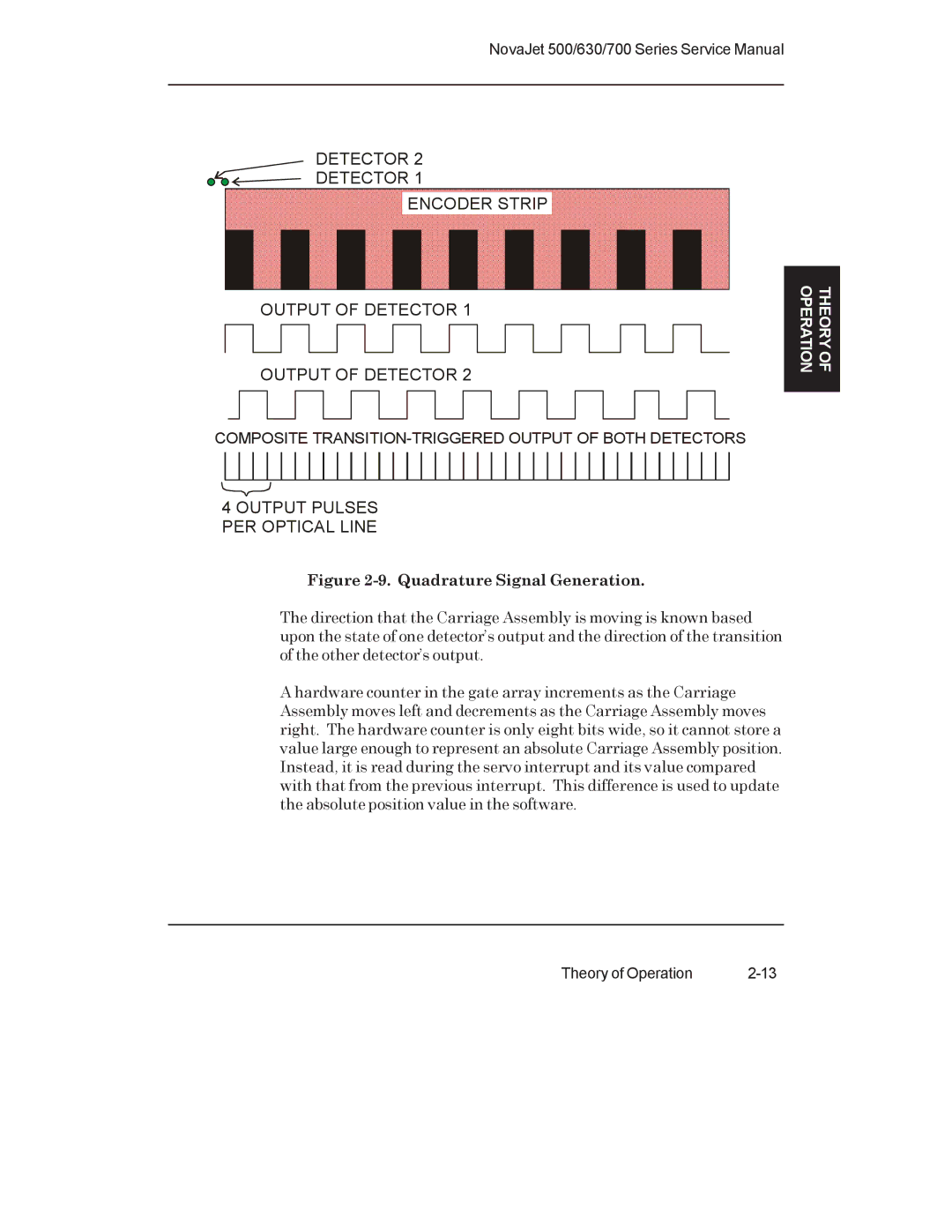
Figure 2-9. Quadrature Signal Generation.
The direction that the Carriage Assembly is moving is known based upon the state of one detector’s output and the direction of the transition of the other detector’s output.
A hardware counter in the gate array increments as the Carriage Assembly moves left and decrements as the Carriage Assembly moves right. The hardware counter is only eight bits wide, so it cannot store a value large enough to represent an absolute Carriage Assembly position. Instead, it is read during the servo interrupt and its value compared with that from the previous interrupt. This difference is used to update the absolute position value in the software.
Theory of Operation |