Main
Printing history
FCC Statement (U.S.A.)
User Instructions:
for NovaJet 736 and 750 FCC Statement (U.S.A.)
User Instructions:
VDE Statement
Material Safety Data Sheet
WARRANTY OR DAMAGE CLAIMS
Table of Contents
Chapter 1 General Description ............................................................ 1-1
Chapter 2 Theory of Operation............................................................ 2-1
Chapter 3 Maintenance ........................................................................ 3-1
Chapter 4 Troubleshooting.................................................................. 4-1
Chapter 3 Maintenance (cont)
Chapter 5 Assembly\Disassembly ...................................................... 5-1
Chapter 4 Troubleshooting (cont)
Chapter 5 Assembly/Disassembly (cont)
List of Illustrations
Chapter 1 General Description
Chapter 2 Theory of Operation
Chapter 3 Maintenance
List of Illustrations (cont)
Chapter 3 Maintenance (cont)
Chapter 4 Troubleshooting
Chapter 5 Assembly/Disassembly
List of Illustrations (cont)
Chapter 5 Assembly/Disassembly (cont)
Chapter 6 Parts List
List of Tables
Page
1
General Description
Page
Overview
Related Publications
Electrostatic Discharge (ESD) Sensitivity
Warnings, Cautions and Notes
WARNING
Printer Specifications
Contents of this Service Manual
Page
Technical Support
2
Theory of Operation
NovaJet 500/630/700 Printers General Block Diagram
2-2 Theory of Operation
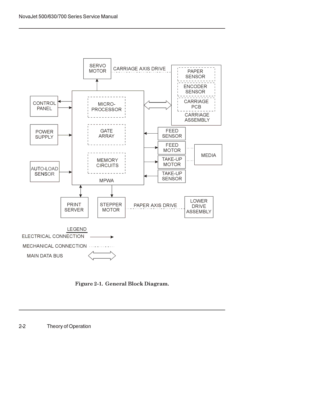
Figure 2-1. General Block Diagram.
Paper (Media) Axis Drive
The Carriage Axis Drive
Media Feed and Take-Up System
Main Printed Wiring Assembly (MPWA)
Microprocessor
Gate Array
Memory Circuits
Flash EEPROM
DRAM
Serial EEPROM
Stepper Motor Controller
Page
Servo Motor Controller
Page
Interface Circuits: Serial & Parallel
Carriage Assembly Circuits
Control Panel
Power Supply
Beeper and Fans
Page
3
Maintenance
Scheduled Maintenance
Cleaning Procedures
WARNING
External Cleaning
Service Station Cleaning
Slide Shaft Cleaning
Linear Encoder Strip Cleaning
Cartridge Jet Area & Dimples Cleaning
Flex Cable Contact Cleaning
Flex Cable Contacts
Clean and Inspect Stepper Motor Gears
Clean and Inspect MPWA
Clean and Inspect Carriage Assembly
Reseat Connectors on MPWA and Carriage Board
Page
Page
Replace Carriage Bushings
Servo Motor Winding Resistance Check
Stepper Motor Winding Resistance Check
Power Feed and Take-Up Motor Winding Resistance Check
Banding: Hardware vs Software
Common Banding Causes
Page
Alignments/Adjustments
Slide Shaft Profile Adjustment
Page
Page
Page
Head Height Alignment Procedure
Page
Page
Page
Color Calibration
Page
Page
Deadband Alignments
Page
Page
Deadband Alignment (for 500 Series)
Color Deadband Alignment (for 630/700 Series)
Page
Paper Axis Calibration
33"
Diagnostics Menu
Page
Page
Limited Access Menu
Firmware Download/Upgrading for the PC
Firmware Download/Upgrading for the MAC
Page
Internal Cabling and Signal Flow Diagrams
MAINTENANCE
Maintenance 3-45
Figure 3-33. MPWA Connections Diagram.
3-46 Maintenance
Figure 3-34. Carriage PWA Connections Diagram.
MAINTENANCE
Maintenance 3-47
Figure 3-35. Leg Harness Connections Diagram.
3-48 Maintenance
Figure 3-36. Leg Harness Connections Diagram (750).
4
Troubleshooting
Page
Page
Page
Page
Page
Page
Page
Page
Page
Page
Page
Page
Page
Page
Page
Page
Initialization Troubleshooting (500 Series)
LED D2
Initialization Troubleshooting (630/700 Series)
Page
Page
5
Assembly\Disassembly
Remove the Left, Top, and Right Covers
Page
Page
Page
Install the Left, Top, and Right Covers
Remove the Keypad and Display
Page
Install the Keypad, Display, and Display Power Converter
Remove Extra Memory (SIMM)
Install Extra Memory (SIMM)
Remove the MPCB (Main Printed Circuit Board)
Page
Page
Install the MPCB
Remove Power Supply, Cooling Fan, and AC Entry Module
Page
Install the Power Supply, Cooling Fan, and AC Entry Module
Remove Servo Motor
Page
Install Servo Motor
Remove the Ink Delivery System
Page
Install the Ink Delivery System
0.10 inch
Remove the Carriage Assembly, Carriage Belt, and the Frame Tensioner
Page
Page
Install the Carriage Assembly, Carriage Belt, and the Frame Tensioner
Page
Remove the Carriage PCB
Page
Install the Carriage PCB
Remove the Paper Sensor or the Encoder Sensor
Page
Install the Paper Sensor or the Encoder Sensor
Replacing the Carriage Bushings
TABS
Remove the Service Station
Install the Service Station
Remove the Trailing Cable Assembly
Install the Trailing Cable Assembly
Remove the Stabilizer Bracket and Encoder Strip
Page
Install the Stabilizer Bracket and Encoder Strip
Remove the Y-Arm Assembly, Pinch Rollers, Slide Shaft, and Auto-Load Sensor
Page
Page
Install the Y-Arm Assembly, Pinch Rollers, Slide Shaft, and Auto-Load Sensor
Remove the Lower Roller Assembly, Stepper Motor and Vacuum Fan
Page
Page
Install the Lower Roller Assembly, Stepper Motor and Vacuum Fan
Page
Page
Remove the Media Take-Up and Feed Sensor Brackets and Sensors
Page
Install the Media Take-Up and Feed Sensor Brackets and Sensors
Remove the Media Take-Up and Feed Motors
Page
Install the Media Take-Up and Feed Motors
Remove the Media Drying Fans
Install the Media Drying Fans
Remove the Thermal Dryer Assembly (NovaJet 750)
WARNING
WARNING
Install the Thermal Dryer Assembly (NovaJet 750)