SLC Advanced Console Manager User Guide
Open Source Software
Warranty
Copyright & Trademark
Contacts
Disclaimer & Revisions
Revision History
Table of Contents
Quick Setup
Web and Command Line Interfaces
Basic Parameters
Services
Device Ports 100
USB/SD Card Port 157
Connections 166
User Authentication 174
Maintenance 227
Command Reference 260
Application Examples 255
Appendix B Safety Information 329
Appendix a Security Considerations 328
SLC 8000 Advanced Console Manager User Guide
List of Tables
List of Figures
SLC 8048 Unit Front Side Part Number SLC 804812N-01-S
13 SSL Certificate97
13User Authentication Custom Menus
About this Guide
Purpose and Audience
Summary of Chapters
Additional Documentation
About this Guide
Introduction
Features
Power
Console Management
System Features
Models
Access Control
Protocols Supported
Hardware Features
Configuration Options
Device Port Buffer
Serial Port Interfaces
Device Ports Back Side
Network Connections
Network Connection
USB Interface
Memory Card Port
Internal Modem
Internal Modem Location
Whats in the Box
Installation
Power Cords
Product Information Label
Technical Specifications
To install the SLC 8000 advanced console manager in a rack
Physical Installation
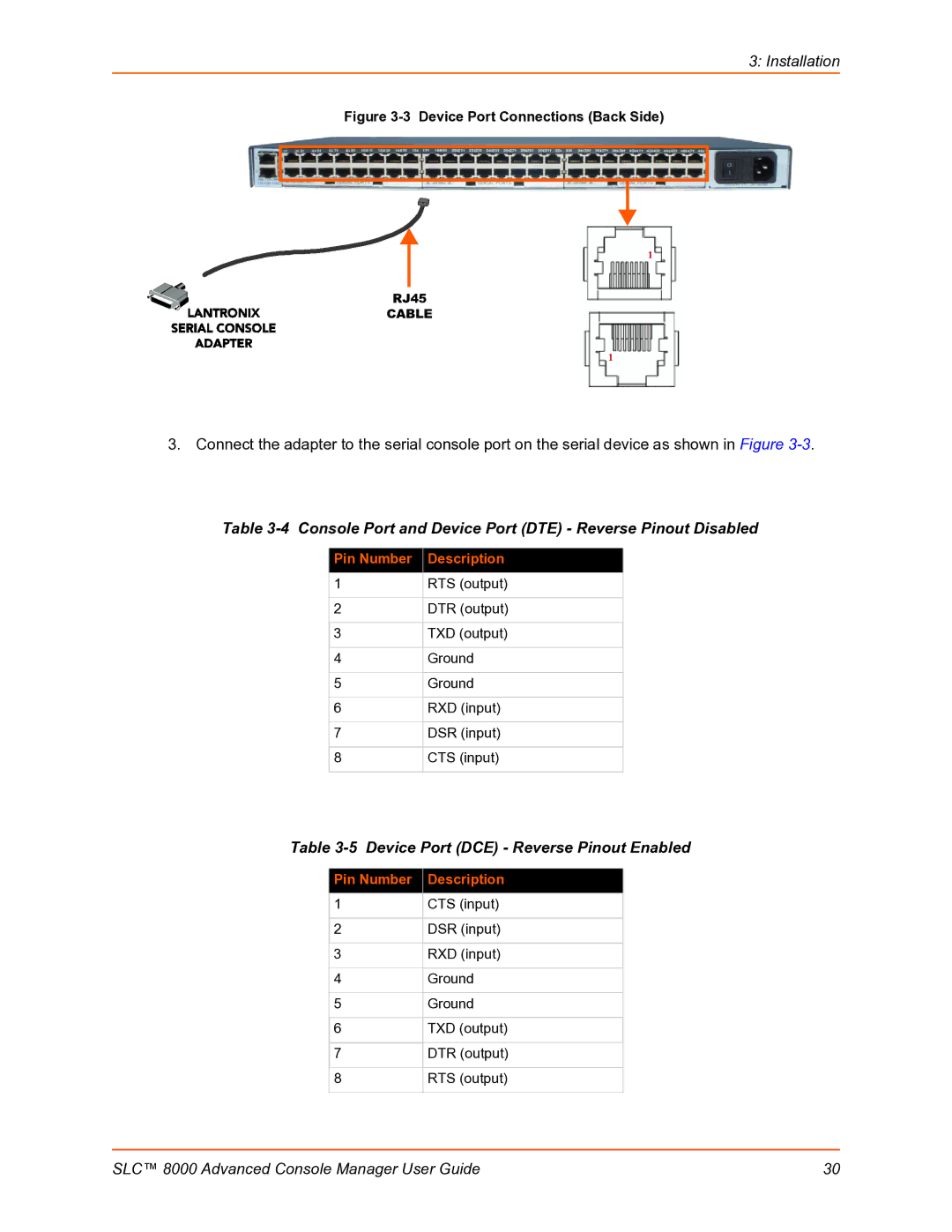
Connecting to a Device Port
To connect to a device port
Console Port and Device Port DTE Reverse Pinout Disabled
Connecting to Network Ports
Connecting Terminals
Modular Expansion for I/O Module
AC Input
To connect a terminal
Modem Installation
Modem Servicing Instructions
Installation
Battery Replacement
Battery Part Numbers
Disposal of Used Batteries from battery data sheet
Battery Replacement Instructions
Short the Battery and Damage the Battery Housing
Installation
Quick Setup
Recommendations
IP Address
Navigating
Method #1 Using the Front Panel Display
Front Panel LCD Display and Keypads
Before you begin, ensure that you have
Enter center button
Right arrow
Left arrow
Up and down arrows
Entering the Settings
To use the LCD display to restore factory default settings
Method #2 Quick Setup on the Web
Restoring Factory Defaults
To complete the Quick Setup
Quick Setup
Network Settings
Date & Time Settings
Method #3 Quick Setup on the Command Line Interface
Administrator Settings
To complete the command line interface Quick Setup script
Config Eth1
IP Address if
Specifying
Sysadmin
Password
Date/Time
Next Step
Web and Command Line Interfaces
Web Manager
Port Number Bar
Logging
To log in to the SLC web manager
Command Line Interface
Logging Out
Web Page Help
Tips
Command Syntax
Command Line Help
To log in any other user
To set the number of lines displayed by a command
General CLI Commands
To configure the current command line session
To show current CLI settings
To view the last 100 commands entered in the session
To clear the command history
To view the rights of the currently logged-in user
Basic Parameters
Requirements
To enter settings for one or both network ports
Network Network Settings
Ethernet Interfaces Eth1 and Eth2
12340BCD1D67000000008375BADD0057 may be shortened to
1234BCD1D678375BADD57
Gateway
Hostname & Name Servers
DHCP-Acquired DNS Servers
Network Commands
DNS Servers
TCP Keepalive Parameters
To view Ethernet port settings and counters
To set the default and alternate network gateways
To view all network settings
To view DNS settings
Mapping Rulesets
IP Filter
Viewing IP Filters
To view a list of IP filters
Enabling IP Filters
Configuring IP Filters
To enable IP filters
To delete a mapping
IP Addresses
Rule Parameters
Ruleset Name
Protocol
Action
Allow service
Port Range
Generate rule to
IP Filter Commands
Updating an IP Filter
Deleting an IP Filter
Dynamic Routing
To configure routing settings
Routing
Replace Rule Number delete Rule Number
Show routing resolveip enabledisable email Email Address
Equivalent Routing Commands
To configure static or dynamic routing
Static Routing
Name
Enable VPN Tunnel
To complete the VPN
Ethernet Port
Remote Id
Authentication IKE
Authentication ESP
Remote Hop/Router
Configuring an IPsec VPN Tunnel through the CLI
Security
To enable Fips
To disable Fips
Services
System Logging and Other Services
SSH/Telnet/Logging
System Logging
Audit Log
Web SSH/Web Telnet Settings
Telnet
Phone Home
Enable Agent
Top Level MIB
Communities
Version
V3 Read-Only User
SNMP, SSH, Telnet, and Logging Commands
Set services one or more services parameters
V3 Read-Write User
Show services
Set services v3passwordv3phrasev3rwpasswordv3rwphrase
To view current services
To configure NFS and SMB/CIFS
SMB/CIFS Share
Nfsserverhostname or ipaddr/exported/path
To mount a remote NFS share
NFS and SMB/CIFS Commands
To view NFS share settings
To unmount a remote NFS share
To view SMB/CIFS settings
Secure Lantronix Network
Show cifs
Services Secure Lantronix Network
To directly access the CLI interface for a device
IP Address Login
To directly access a specific port on a particular device
SSH or Telnet CLI Session
Add IP Address delete IP Address
Secure Lantronix Network Commands
Set s one or more parameters
Secure Lantronix
Show slcnetwork ipaddrlist allAddress Mask
Date and Time
Search localsubnetipaddrlistboth
To set the local date, time, and time zone
10 Services Date & Time
Enable NTP
Date and Time Commands
To view the local date, time, and time zone
Web Server
To view NTP settings
To configure the Web Server
Show ntp
Admin web timeout disable5-120 minutes
Admin Web Commands
To configure the timeout for web sessions
Admin web protocol sslv2nosslv2
Services Web Sessions
Services SSL Certificate
To view, reset, import, or change an SSL Certificate
Certificate
Reset to Default
Login
Import SSL Certificate
Password / Retype Password
Web Server Commands
To set up an SLC iGoogle gadget
IGoogle Gadgets
14 iGoogle Gadget Example
Device Ports
Connection Methods
Permissions
Modules
Device Ports
Device Status
Devices Device Status
Device Ports
Devices Device Ports
Global Commands
Telnet/SSH/TCP in Port Numbers
To open the Device Ports Settings
Device Ports Settings
To view global settings for device ports
Sshport TCP Port tcpport TCP Port telnetport TCP Port
SLC 8000 Advanced Console Manager User Guide 106
Device Port Settings
IP Settings
Data Settings
Hardware Signal Triggers
Modem Settings Device Ports
Modem Settings Text Mode
Modem Settings PPP Mode
AT S7=45 SO=0 L1 V1 X4 &D2 &c1 E1 Q0
Enable NAT
Same authentication for
DOD Authentication
Remote/Dial-out Login
Port Status and Counters
Device Ports SLP / ServerTech CDU Device
To open the Device Ports SLP
Number of Expansion
To enter SLP commands
Number of Outlets
Outlets
Device Port Sensorsoft Device
Devices Device Ports Sensorsoft
Device Port Commands
To set the dialout password
To view the settings for one or more device ports
Show deviceport port Device Port List or Name
To view the modes and states of one or more device ports
Device Commands
To view a list of all device port names
To zero the port counters for one or more device ports
Interacting with a Device Port
To connect to a device port to monitor it
NFS File Logging
Device Ports Logging
Local Logging
Connect direct endpoint
Sylog Logging
USB and SD Card Logging
Email/SNMP Notification
Device Port NumberDevice Port NameFile number.log
Email/Traps
Local Logging
Email/Traps
Trigger on
Email Delay
Send
Byte Threshold
Log Viewing Attributes
USB / SD Card Logging
Syslog Logging
Show locallog Device Port # or Name bytes Bytes To Display
Logging Commands
To configure logging settings for one or more device ports
To clear the local log for a device port
Console Port
To set console port parameters
To configure console port settings
Internal Modem Settings
Console Port Commands
To view console port settings
Setting Up Internal Modem Storage
SLC 8000 Advanced Console Manager User Guide 128
AT S7=45 SO=0 L1 V1 X4 &D2 &c1 E1 Q0
To add a host list
Password/ Retype
Host Lists
Chap Handshake
To retry connecting to the host list
Host Parameters
Escape Sequence
To view or update a host list
Retry connecting to the host list
Host List Commands
To delete a host list
To add a new host entry to a list or edit an existing entry
To display the members of a host list
Scripts
To move a host entry to a new position in the host list
To add a script
SLC 8000 Advanced Console Manager User Guide 136
Scripts
Script Name
Type
User Rights
To view or update a script
SD Card Right to view and enter settings for SD card
Group
To delete a script
Batch Script Syntax
To rename a script
To change the permissions for a script
Senduser Password
Interface Script Syntax
Set myvar expr 1 +
Primary Commands
Secondary Commands
String match str 1 str
String compare str 1 str
Compare two strings
Determine if two strings are equal
Control Flow Commands
19 Control Flow Commands
Sample Scripts
Interface Script-Monitor Port
SLC 8000 Advanced Console Manager User Guide 146
Batch Script-SLC CLI
SLC 8000 Advanced Console Manager User Guide 148
Site Id
Sites
To add a site
Site Name
Dial-out Password
Login/CHAP Host
Dial-out Login
Chap Secret
To create or edit a site
To view or update a site
To delete a site
Set site addedit Site Name parameters
Modem Dialing States
Dial
Set site delete Site Name show site allnamesSite Name
Dial-back
Dial-on-demand
Dial-in & Dial-on-demand
Dial-back & Dial-on-demand
Cbcp Server
SLC 8000 Advanced Console Manager User Guide 156
Set Up of USB/SD Card Storage
USB/SD Card Port
Click Configure
Filesystem
Unmount
Format
Filesystem Check
To configure the USB Modem port, from the USB Ports table
Devices USB Modem
Modem Settings
Text Mode
PPP Mode
Remote/Dial-out Pwd
Manage Files
USB Commands
SD Card Commands
Typical Setup Scenarios for the SLC Unit
Connections
Terminal Server
Remote Access Server
Reverse Terminal Server
Multiport Device Server
Console Server
Outgoing
Connection Configuration
To create a connection
Connection
Options
To view, update, or disconnect a current connection
SSH Out
Trigger
Connection Commands
To configure initial timeout for outgoing connections
To monitor a device port
To terminate a bidirectional or unidirectional connection
To view connections and their IDs
To display details for a single connection
To display global connections
Connect global show
User Authentication
Ldap
User Authentication Authentication Methods
Kerberos
Set auth one or more parameters
Authentication Commands
To set ordering of authentication methods
Show auth
User Rights
User Types and Rights
Local and Remote User Settings
To enable local and/or remote users
Adding, Editing or Deleting a User
To add a user
Listen Ports
Data Ports
Clear Port Buffers
Password Expires
Enable for Dial-back
Display Menu at Login
Allow Password Change
SD Card Right to enter settings for SD card
Select or clear the checkboxes for the following rights
Local Users Commands
Shortcut
Local User Rights Commands
Remote User Commands
To view settings for all remote users
To configure the SLC unit to use NIS to authenticate users
User Authentication NIS
Broadcast for NIS
Enable NIS
NIS Domain
NIS Master Server
SLC 8000 Advanced Console Manager User Guide 188
NIS Commands
To view NIS settings
To set group and permissions for NIS users
To configure the SLC unit to use Ldap to authenticate users
Ldap
User Authentication Ldap
Enable Ldap
Uid=$login,ou=People,dc=lantronix,dc=com, and user roberts
Uid=roberts,ou=People,dc=lantronix,dc=com and the password
Certificate in base64 encoding
Key File is in PEM format, eg
Private key in base64 encoding
Right to enter modem settings for USB
Ldap Commands
Adsupport enabledisable
Set ldap one or more parameters
To set user group and permissions for Ldap users
To set the Ldap bind password
To view Ldap settings
To import or delete a certificate
Radius
Tcp, or udp
Listen Port
Radius Commands
To set user group and permissions for Radius users
To view Radius settings
Show radius
Kerberos
END-VENDOR Lantronix
Enable Kerberos
Realm
KDC IP Address
Full Administrative
KDC Port
Use Ldap
Set kerberos one or more parameters
Kerberos Commands
Set kerberos group defaultpoweradmin
To set user group and permissions for Kerberos users
Set kerberos custommenu Menu Name
To view Kerberos settings
Set kerberos permissions Permission List
Show kerberos
Enable TACACS+
TACACS+ Servers
Secret
SLC 8000 Advanced Console Manager User Guide 207
Set tacacs+ one or more parameters
TACACS+ Commands
Set tacacs+ group defaultpoweradmin
To set user group and permissions for TACACS+ users
Groups
To view TACACS+ settings
To configure Groups in the SLC unit
Set tacacs+ custommenu Menu Name
10 User Authentication Groups
Group Name
Enable for
Deviceport, tcp, or udp
Dial-back
SSH Keys
Imported Keys
Exported Keys
SLC 8000 Advanced Console Manager User Guide 214
Exported Keys SSH Out
Host & Login for Import
Imported Keys SSH
Host & User Associated with Key
To view or delete a key
Host and Login for Export
To view, reset, or import SSH RSA1, RSA, And DSA host keys
Key Name
Reset to Default Host
Key
Import Host Key
Set sshkey import ftpscpcopypaste one or more parameters
SSH Commands
To import an SSH key
To export a key
To display SSH keys that have been imported
To reset defaults for all or selected host keys
To delete a key
To display SSH keys that have been exported
Custom Menus
To add a custom menu
SLC 8000 Advanced Console Manager User Guide 221
Nicknames
Menu Name
Title
Redisplay Menu
To delete a custom menu
Custom User Menu Commands
To view or update a custom menu
To create a new custom menu from an existing custom menu
To set the optional title for a menu
SLC 8000 Advanced Console Manager User Guide 225
SLC 8000 Advanced Console Manager User Guide 226
Maintenance
Firmware & Configurations
To configure settings
Maintenance Firmware & Configurations
Internal Temperature
Site Information
SLC Firmware
Boot Banks
Load Firmware Via Options
Configuration Management
Admin shutdown
Administrative Commands
To reboot the SLC 8000 advanced console manager
Manage Files
To restore the SLC unit to factory default settings
To update SLC firmware to a new revision
To view FTP settings
To list current hardware and firmware information
To list the configurations saved to a location
To rename a saved configuration
To delete a saved configuration
Set temperature one or more parameters
Level
System Logs
To view system logs
Starting at
System Log Command
To clear system logs
Ending at
Audit Log
To clear one or all of the system logs
SLC 8000 Advanced Console Manager User Guide 238
Maintenance Email Log
Email Log
Netstat
Diagnostics
ARP Table
Host Lookup
Diagnostic Commands
Diag arp email Email Address
To verify that the host is up and running
To display a report of network connections
To resolve a host name into an IP address
To generate and send Ethernet packets
Diag nettrace one or more parameters
Default is
To display all network traffic, applying optional filters
Parameters ethport
Maintenance Status/Reports
Status/Reports
All Displays all reports Port Status
Serial port settings
View Report
Devices Host Lists
Emailing Logs and Reports
Status Commands
To display a snapshot of configurable parameters
To display the overall status of all SLC units
To email a log to an individual
11 Emailed Log or Report
SLC 8000 Advanced Console Manager User Guide 248
Events
Event Trigger
Ethernet
Events Commands
LCD/Keypad
To update event definitions
To configure the LCD and Keypad
To delete an event
To configure the LCD
To configure the Keypad
Keypad Locked
Restore Factory Defaults Password / Retype Password
LCD/Keypad Commands
To configure banner settings
Banners
Welcome Banner
Banner Commands
Login Banner
Logout Banner
Application Examples
Telnet/SSH to a Remote Device
SLC show deviceport port
Reboot Shutdown messages from SUN
SLC connect direct deviceport
Dial-in Text Mode to a Remote Device
Dial-in Text Mode to a Remote Device
Local Serial Connection to Network Device via Telnet
Local Serial Connection to Network Device via Telnet
Trying Connected to Escape character is Sun OS 8.0 login
Command Reference
Introduction to Commands
For general command line Help, type
Admin banner logout
Administrative Commands
Admin banner login
Admin banner show
Admin config delete
Admin banner ssh
Admin banner welcome
Admin config factorydefaults
Admin config restore
Admin config save
Admin firmware show
Admin config show
Admin firmware bootbank
Admin firmware update
Admin ftp show
Admin ftp password
Admin ftp server
Admin keypad
Admin memory show
Admin keypad show
Admin lcd reset
Admin memory swap add Size of Swap in MB usbport U1U1
Admin shutdown
Admin quicksetup
Admin reboot
Admin site
Admin web certificate reset
Admin version
Admin web certificate
Admin web certificate show
Admin web terminate
Admin web group
Admin web timeout
Admin web show
Audit Log Commands
Show auth
Authentication Commands
Set auth
Show user
Set kerberos
Kerberos Commands
Displays Kerberos settings
Show kerberos
Ldap Commands
Set ldap bindpassword
Set ldap
Set ldap certificate importdelete
Local Users Commands
Set localusers addedit User Login one or more parameters
Show ldap
Set localusers state
Set local users complexpasswords
Set localusers allowreuse
Set localusers delete
Set localusers periodlockout
Set localusers maxloginattempts
Set localusers password
Set localusers periodwarning
NIS Commands
Show localusers
Set nis
Show nis
Radius Commands
Displays NIS settings
Set radius
Set radius server
TACACS+ Commands
Displays Radius settings
Show radius
Set localusers group
User Permissions Commands
Show tacacs+
Set localusers lock
Set localusers permissions
Set remoteusers addedit
Set remoteusers listonlyauth
Set nisldapradiuskerberostacacs+ group
Set remoteusers delete
Show remoteusers
Set nisldapradiuskerberostacacs+ permissions
CLI Commands
Set cli
Set cli terminallines
Set history
Connection Commands
Show cli
Show history
Connect global outgoingtimeout
Connect direct
Connect listen deviceport
Connect terminate
Connect unidirection
Show connections
Show connections connid
Set consoleport
Set localusers
Custom User Menu Commands
Show consoleport
Set menu add
Show menu
Set menu delete
Set nisldapradiuskerberostacacs+ custommenu
Set nisldapradiuskerberostacacs custommenu Menu Name
Show datetime
Date and Time Commands
Set datetime
Set ntp
Device Commands
Set command
Show ntp
Device Port Commands
Set deviceport port
SLC 8000 Advanced Console Manager User Guide 294
Show deviceport names
Set deviceport global
Show deviceport global
Sshport TCP Port telnetport TCP Port tcpport TCP Port
Show portcounters zerocounters
Show deviceport port
Show portcounters
Show portstatus
Diag internals
Diagnostic Commands
Diag arp
Diag netstat
Diag perfstat
Diag lookup
Diag loopback
Diag pingping6
Diag top
Count=1, delay = 5 seconds
Diag sendpacket host
Diag traceroute
Slp envmon
End Device Commands
Slp auth login
Slp outletcontrol state
Slp restart
Events Commands
Admin events add
Slp system
Admin events edit
Group Commands
Admin events delete
Admin events show
Set hostlist addedit Host List Name entry
Host List Commands
Set hostlist addedit Host List Name
Set groups rename Group Name newname New Group Name
Set hostlist edit Host List Name move
Set hostlist delete
Show hostlist
Internal Modem Commands
Set ipfilter state
Set ipfilter mapping
Logging Commands
Set ip filter rules
Show locallog
Set locallog clear
Example
Set log modem ppplog enabledisable
Set log modem pppdebug enabledisable
Set log clear modem
Set network
Network Commands
Show log local
Set network dns
Set network host
Configures up to three DNS servers
Set network gateway
Set network port
Show network host
Displays all network settings
Show network gateway
Show network port
Set nfs unmount
NFS and SMB/CIFS Commands
Set nfs mount
Set cifs
Show cifs
Routing Commands
Set cifs password
Show nfs
Show routing
Security Commands
Services Commands
Show services
Set slcnetwork
SLC Network Commands
SSH Key Commands
Show slcnetwork
Set sshkey import
Set sshkey delete
Set sshkey export
Set sshkey import
Show sshkey export
Set sshkey server reset
Set sshkey server import type
Show sshkey import
Status Commands
Show sshkey server
Show sysstatus
System Log Commands
Show sysconfig
Show syslog
Set usb access
USB Access Commands
USB Storage Commands
Show syslog clear
Set usb storage mount
Set usb storage fsck
Set usb storage format
Set usb storage unmount
Set usb storage delete
USB Modem Commands
Set usb storage copy
Show usb storage
Set vpn
VPN Commands
Set usb modem U1U2 dialoutpassword
Show usb modem
Show vpn
Set temperature
Set temperature
Show temperature
Show vpn rsakey
Appendix a Security Considerations
Security Practice
Factors Affecting Security
Appendix B Safety Information
Safety Precautions
Rack
Port Connections
Appendix C Adapters and Pinouts
Appendix C Adapters and Pinouts
SLC 8000 Advanced Console Manager User Guide 333
Appendix D Protocol Glossary
TACACS+ Terminal Access Controller Access Control System
PAP Password Authentication Protocol
Radius Remote Authentication Dial-In User Service
NTP Network Time Protocol
Appendix E Compliance Information
Manufacturer’s Name & Address
Appendix E Compliance Information
RoHS Notice