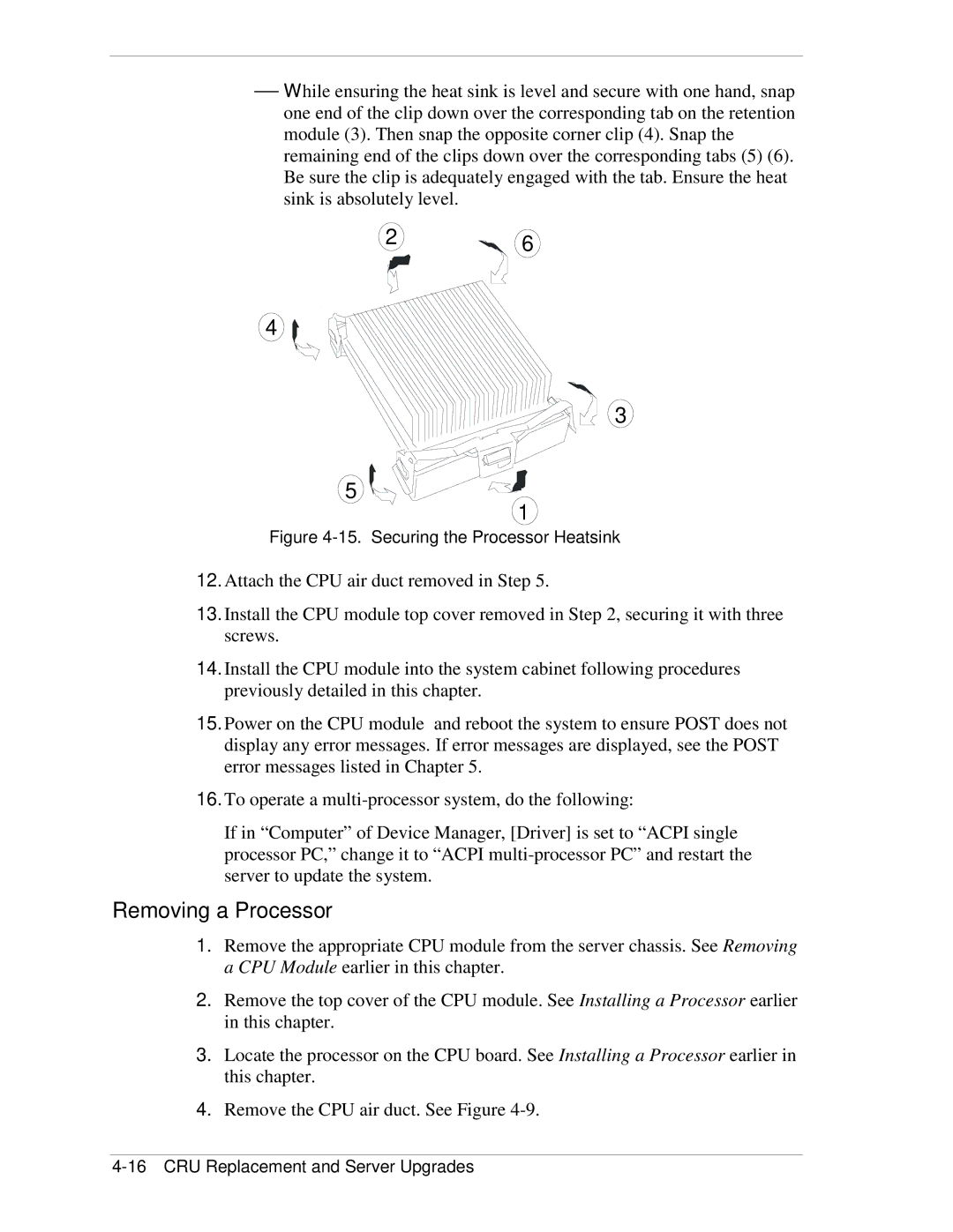
While ensuring the heat sink is level and secure with one hand, snap one end of the clip down over the corresponding tab on the retention module (3). Then snap the opposite corner clip (4). Snap the remaining end of the clips down over the corresponding tabs (5) (6). Be sure the clip is adequately engaged with the tab. Ensure the heat sink is absolutely level.
26
4
3
5
1
Figure 4-15. Securing the Processor Heatsink
12.Attach the CPU air duct removed in Step 5.
13.Install the CPU module top cover removed in Step 2, securing it with three screws.
14.Install the CPU module into the system cabinet following procedures previously detailed in this chapter.
15.Power on the CPU module and reboot the system to ensure POST does not display any error messages. If error messages are displayed, see the POST error messages listed in Chapter 5.
16.To operate a
If in “Computer” of Device Manager, [Driver] is set to “ACPI single processor PC,” change it to “ACPI
Removing a Processor
1.Remove the appropriate CPU module from the server chassis. See Removing a CPU Module earlier in this chapter.
2.Remove the top cover of the CPU module. See Installing a Processor earlier in this chapter.
3.Locate the processor on the CPU board. See Installing a Processor earlier in this chapter.
4.Remove the CPU air duct. See Figure
