Installing PCI Adapter Boards
This subsection describes how to install PCI adapter boards. Use these procedures when adding or replacing PCI adapter boards in your system. When adding, but not replacing a PCI adapter board in a PCI module an identical PCI adapter board must be added to the other PCI module to continue total system redundancy and mirroring.
![]() Notes: All installed PCI adapter boards must have the same specifications and performance characteristics in order to provide total system redundancy and mirroring.
Notes: All installed PCI adapter boards must have the same specifications and performance characteristics in order to provide total system redundancy and mirroring.
The PCI module board, is located in the PCI module and can have up to two 64- bit PCI adapter boards and one
![]() Note: PCI expansion slot #1 is dedicated to the standard video graphics board.
Note: PCI expansion slot #1 is dedicated to the standard video graphics board.
!CAUTION
Electrostatic discharge (ESD) can damage components; place them on an antistatic surface. Only handle PCI adapter boards using an antistatic wrist strap attached to chassis ground.
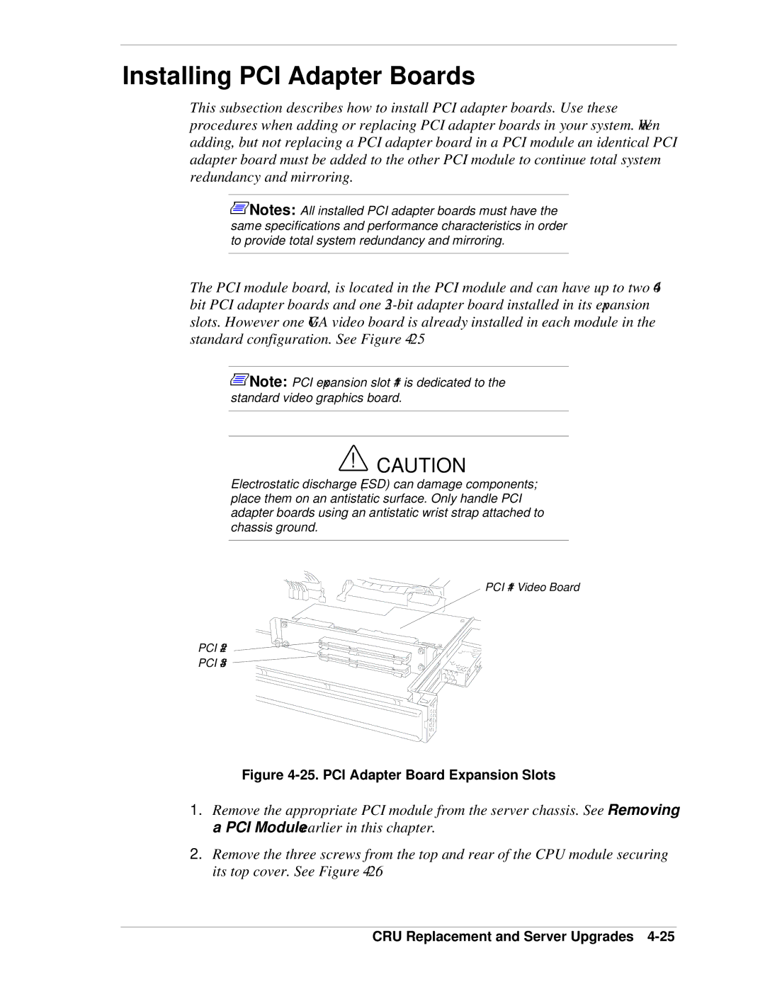
PCI #1 Video Board
PCI #2
PCI #3
Figure 4-25. PCI Adapter Board Expansion Slots
1.Remove the appropriate PCI module from the server chassis. See Removing a PCI Module earlier in this chapter.
2.Remove the three screws from the top and rear of the CPU module securing its top cover. See Figure