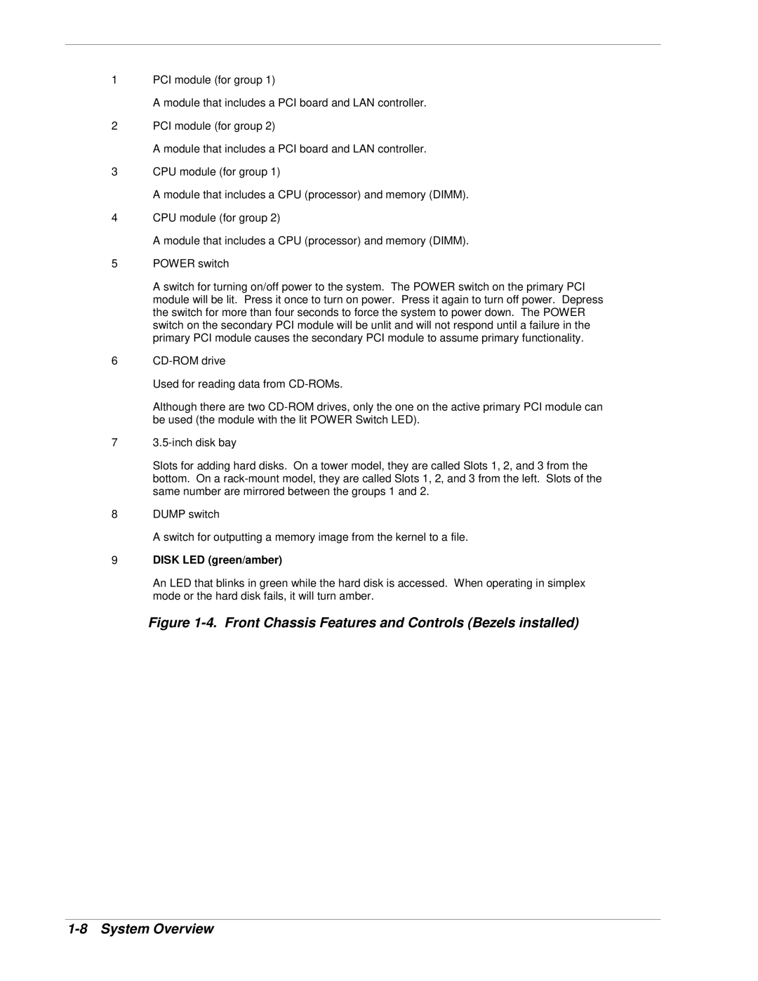
1PCI module (for group 1)
A module that includes a PCI board and LAN controller.
2PCI module (for group 2)
A module that includes a PCI board and LAN controller.
3CPU module (for group 1)
A module that includes a CPU (processor) and memory (DIMM).
4CPU module (for group 2)
A module that includes a CPU (processor) and memory (DIMM).
5POWER switch
A switch for turning on/off power to the system. The POWER switch on the primary PCI module will be lit. Press it once to turn on power. Press it again to turn off power. Depress the switch for more than four seconds to force the system to power down. The POWER switch on the secondary PCI module will be unlit and will not respond until a failure in the primary PCI module causes the secondary PCI module to assume primary functionality.
6
Used for reading data from
Although there are two
7
Slots for adding hard disks. On a tower model, they are called Slots 1, 2, and 3 from the bottom. On a
8DUMP switch
A switch for outputting a memory image from the kernel to a file.
9DISK LED (green/amber)
An LED that blinks in green while the hard disk is accessed. When operating in simplex mode or the hard disk fails, it will turn amber.