Replacing or Adding DIMMs
The following subsections provide the procedures for configuring and upgrading system memory. Use these procedures when replacing or adding dual inline memory modules (DIMMs) to your system. When adding or changing memory in a CPU module the same changes must be must be made to the other CPU module to provide total system redundancy and mirroring.
The CPU board contains six DIMM sockets (see Figure
![]() Note: When replacing or upgrading DIMMs the replacement DIMMs must be of the same specifications of all the installed DIMMs.
Note: When replacing or upgrading DIMMs the replacement DIMMs must be of the same specifications of all the installed DIMMs.
!CAUTION
Electrostatic discharge (ESD) can damage components; place them on an antistatic surface. Add or replace DIMMs on the CPU board using an antistatic wrist strap attached to chassis ground.
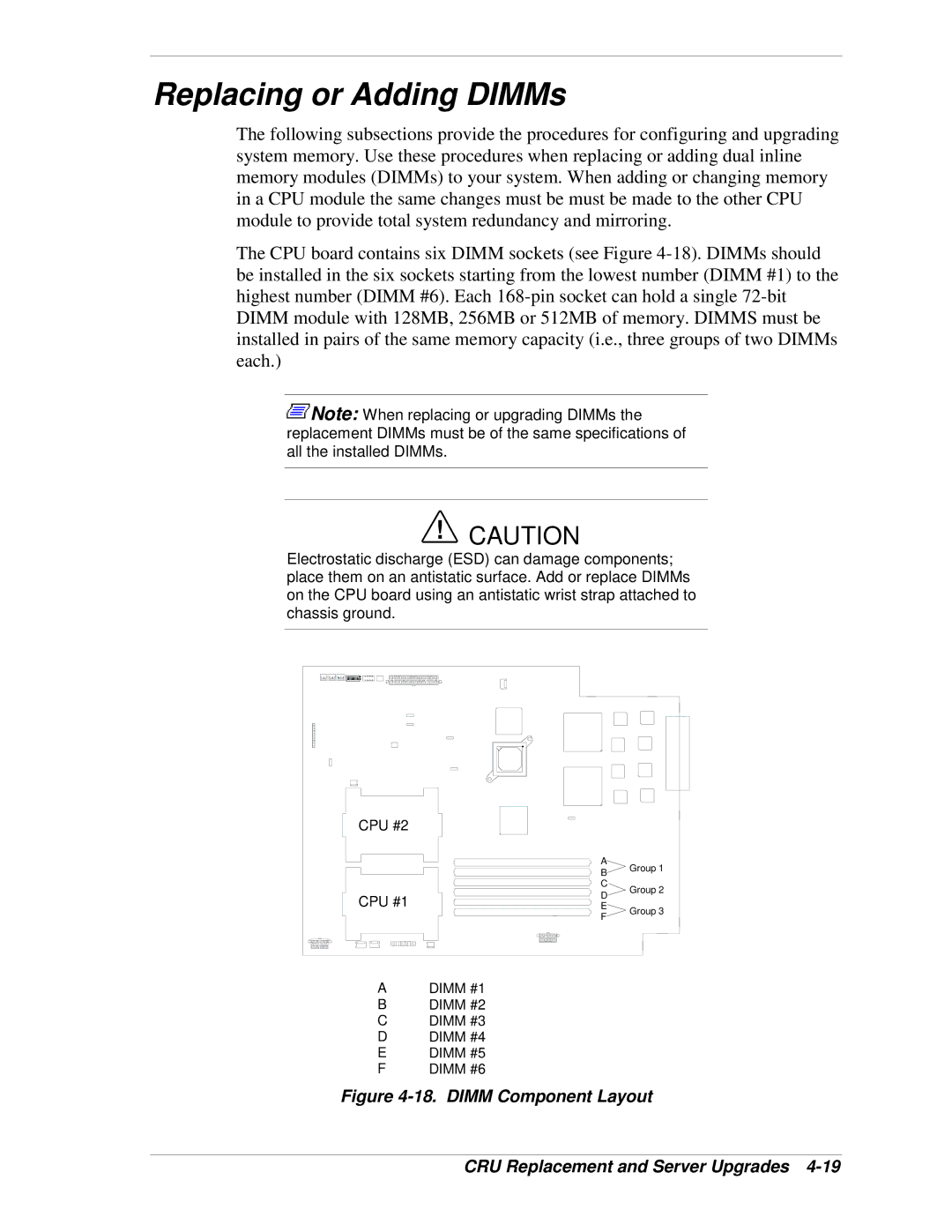
CPU #2
CPU #1
ADIMM #1
BDIMM #2
CDIMM #3
DDIMM #4
EDIMM #5
FDIMM #6
A | Group 1 | |
B | ||
C | Group 2 | |
D | ||
| ||
E | Group 3 | |
F | ||
|