CPU Module LEDs
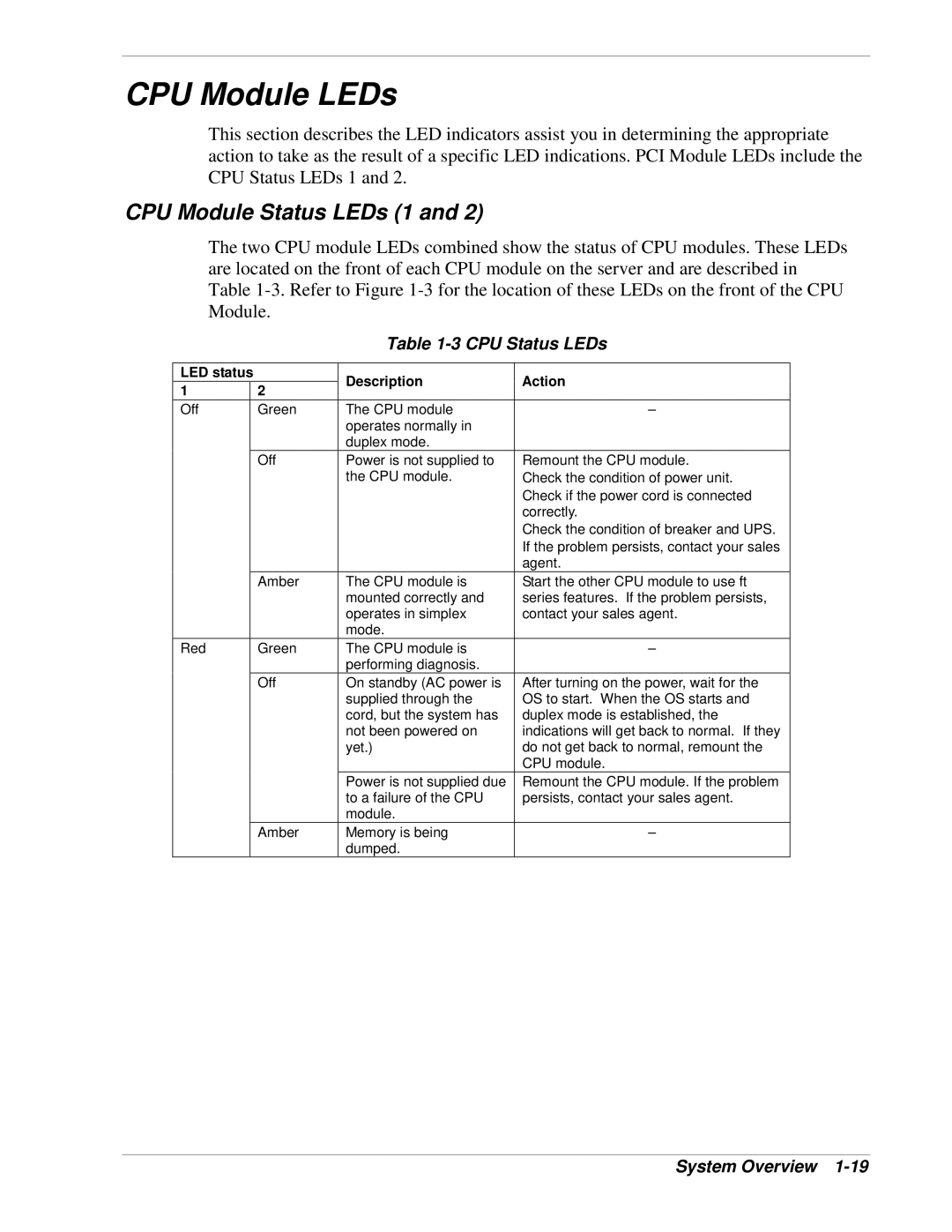
This section describes the LED indicators assist you in determining the appropriate action to take as the result of a specific LED indications. PCI Module LEDs include the CPU Status LEDs 1 and 2.
CPU Module Status LEDs (1 and 2)
The two CPU module LEDs combined show the status of CPU modules. These LEDs are located on the front of each CPU module on the server and are described in Table
Table 1-3 CPU Status LEDs
LED status |
| Description | Action | |
1 |
| 2 | ||
|
|
| ||
Off |
| Green | The CPU module | – |
|
|
| operates normally in |
|
|
|
| duplex mode. |
|
|
| Off | Power is not supplied to | Remount the CPU module. |
|
|
| the CPU module. | Check the condition of power unit. |
|
|
|
| Check if the power cord is connected |
|
|
|
| correctly. |
|
|
|
| Check the condition of breaker and UPS. |
|
|
|
| If the problem persists, contact your sales |
|
|
|
| agent. |
|
| Amber | The CPU module is | Start the other CPU module to use ft |
|
|
| mounted correctly and | series features. If the problem persists, |
|
|
| operates in simplex | contact your sales agent. |
|
|
| mode. |
|
Red |
| Green | The CPU module is | – |
|
|
| performing diagnosis. |
|
|
| Off | On standby (AC power is | After turning on the power, wait for the |
|
|
| supplied through the | OS to start. When the OS starts and |
|
|
| cord, but the system has | duplex mode is established, the |
|
|
| not been powered on | indications will get back to normal. If they |
|
|
| yet.) | do not get back to normal, remount the |
|
|
|
| CPU module. |
|
|
| Power is not supplied due | Remount the CPU module. If the problem |
|
|
| to a failure of the CPU | persists, contact your sales agent. |
|
|
| module. |
|
|
| Amber | Memory is being | – |
|
|
| dumped. |
|
