1005r Server Maintenance and Diagnostics
Copyright 2007 Nortel Networks
June
Following applies to server models 703t and 1002rp
Japan Denan statement
Japan Vcci statement
Following applies to server models 703t, 201i, and 1002rp
June
Standard
General release
CallPilot 4.0, Standard 1.10 of the 1005r Server
CallPilot 4.0, Standard 1.09 of the 1005r Server
CallPilot 4.0, Standard 1.08 of the 1005r Server
Publication history
Task List
127
Contents
Using CallPilot system utilities
Index 197
Contents Standard
Getting Help over the phone from a Nortel Solutions Center
How to get Help
A p t e r
Getting Help from the Nortel Web site
Getting Help through a Nortel distributor or reseller
This chapter
Outlining maintenance and diagnostics activities
Front control panel and features
1005r server features
Front panel controls
ID switch Hard drive 1 release lever
Back panel controls and features
DB15 Telco alarm RJ45 NIC 1 connector Connector not used
Hard drive 0 pull handle
June 2007Outlining maintenance and diagnostics activities
Maintenance and diagnostics overview
Preparing for maintenance activities
Replacement parts
CallPilot Customer Documentation Map
Reference documents
Troubleshooting your CallPilot system
Types of startup diagnostics
Startup diagnostics overview
To run the startup test
Basic hardware check
Alarm fault LEDs
June
To run the Post
Power-On Self-Test diagnostics
Interpreting Post diagnostics
Post beep codes
Post beep codes
Bios error messages
Interpreting Bios error messages
June 2007Troubleshooting your CallPilot system
Last boot. If you did not add or remove
NVRAM, CMOS, and passwords have
Nvram / Cmos / Password
To determine why the server fails to boot to Windows
What to do when the server fails to boot into service
To determine why CallPilot fails to come into Service
If CallPilot fails to boot to Windows, follow these steps
June
To immediately
Interpreting hard drive LEDs
Performing a hardware shutdown
Troubleshooting your CallPilot system Standard
Using Windows online diagnostic tools
Overview
Viewing event logs
Types of Windows event logs
Event Viewer
To use the operating system Event Viewer
Application log
System log
Ipconfig command
Using TCP/IP diagnostic tools
Ipconfig command displays IP configuration information
Ipconfig default
Ipconfig command syntax
To run the ipconfig command from Windows
Ipconfig command extensions
Ping command syntax
Ping command
Ping command extensions
Tracert command
To run the ping command from Windows
This utility determines the route taken to a destination
How tracert works
Tracert parameters
To run the tracert command from Windows
Tracert syntax
Tracert parameters
ARP command parameters
Arp command
ARP command syntax
ARP command parameters
Nbtstat command
To run the arp command from Windows
Nbtstat command syntax
Nbtstat command uses the following syntax
Nbstat command parameters
Nbstat command parameters
To run the nbtstat command from Windows
Netstat command parameters
Netstat command
Netstat command syntax
Netstat command parameters
Chkdsk utility syntax
Using the chkdsk utility
Chksdsk utility parameters
Chkdsk utility uses the following syntax
To run the chkdsk utility from Windows
Using Windows online diagnostic tools Standard
Monitoring server hardware
ISM overview
Monitoring multimedia hardware
Alarm notification
Understanding fault management
Event processing
Component dependencies
All DS30X channels associated with the DS30X link
Detecting hardware problems
All multimedia channels on the MPB96 card
About alarms
Alarm Monitor
To investigate using the Alarm Monitor
Alarm monitor screen
About events
To investigate using the Event Browser
Event Browser
Event Browser screen
Disabling call channels
Channel and Multimedia Monitors
What the Maintenance screen provides
Maintenance screen
Partially expanded tree for 1005r
Component sections
Maintenance activities
Maintenance activities for each component
Component states
Viewing component states
Duty state
This state occurs quickly and is immediately
Alert icons
To view the state of a hardware component
Starting and stopping components
Components that you can start and stop
Stop versus courtesy stop
Courtesy stop
Stop
To start or stop a component
Web messaging users so that they can log off
Components with diagnostic tests available
Running integrated diagnostics
Take the component out of service before you run
Diagnostic test. See Starting and stopping components
If a diagnostic test fails or cannot be run
To run a diagnostic test
Diagnostic tests available for each component
Monitoring multimedia hardware Standard
To view the last diagnostics result
Viewing the last diagnostics result
Monitoring multimedia hardware Standard
To view or work with multimedia channel states
Working with the Multimedia Monitor
All of the channels
To view or work with call channel states
Working with the Channel Monitor
All of the channels associated with
Using CallPilot system utilities
Removal
Accessing the system utilities
Following table lists the CallPilot system utilities
To access the Diagnostics Tool
Diagnostics Tool
To enable startup diagnostics
To disable startup diagnostics
Maintenance Startup Diag Disable
To view a list of all installed PEPs
PEP Maintenance utility
To access the PEP Maintenance utility
Session Trace
To access the session trace tool
To find a session
Call Answering session
CallPilot System Monitor
To access the CallPilot System Monitor
System Monitor tabs
Channel Monitor tab
Channel Monitor with M1
CallPilot services
CallPilot Slee Service
Ctms Service Ctms Server Telephony Tapi Telephony Service
CallPilot Call Channel Router
CallPilot Blue Call Router
DS30X links
System Info tab
System Info tab
104 CallPilot
Replacing basic chassis components
To remove the front bezel
Removing and replacing the front bezel
To replace the front bezel
High current inside the chassis can cause severe injury
Removing and replacing the server cover
To remove the server cover
Server cover
To replace the server cover
To remove the processor air duct
Removing and replacing the processor air duct
Requirements
You need a Phillips cross head screwdriver, #1 and #2 bit
Processor air duct
To replace the processor air duct
When to hot-swap the power supply
Replacing the power supply
To hot-swap a power supply
Power supplies
To replace a Scsi hard drive
Replacing a hard drive
Front panel
Scsi hard drive carrier
Hard disk drive location in carrier
When to replace the cooling fan assembly
Replacing the four-fan assembly
To replace the four-fan assembly
Cooling fan assembly
Replacing the dual NIC card
To replace a dual NIC card
DS30X cables for high capacity
Scsi cable attached to RAID card
PCI riser card assembly
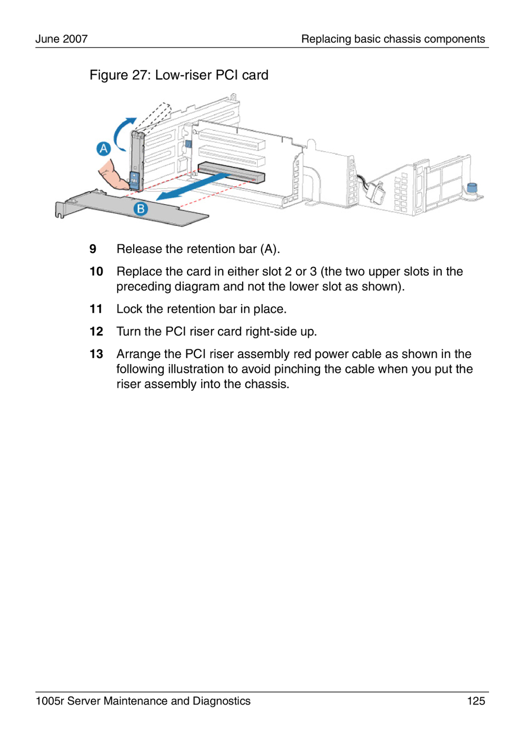
Low-riser PCI card
Malfunction
PCI riser assembly power cord
PCI riser assembly rear grooves
128 CallPilot
To replace the DVD combo drive
Replacing the DVD combo drive
DVD combo drive assembly
1005r Server Maintenance and Diagnostics 131
To replace the Dimm cards
Replacing memory DIMMs
Memory Dimm locations
134 CallPilot
To replace the software feature key
Replacing the software feature key
Inserting the feature key
RAID operations
Outlining RAID functions
RAID configuring and splitting
Verifying the RAID firmware
Launch MegaRAID Power Console Plus
To verify the RAID firmware version
Press Ctrl+M
To upgrade or downgrade the RAID firmware
System will now reboot. Press any key to continue
To configure RAID, do the following
Configuring RAID using LSI320-1 controller and Ctrl+M
To configure an LSI320-1 RAID system
1005r Server Maintenance and Diagnostics 143
RAID
To perform a consistency check
Verifying consistency on the drives
Result An end of session message appears Click OK
To split the RAID
RAID splitting
Do not make the failed drive online at this point, or data
RAID synchronization after installing a PEP
Corruption can occur. If you failed the wrong drive by
Mistake, you must select rebuild to bring it back into
To synchronize the RAID after a successful PEP installation
Or data corruption can occur
Do not use the Power Console for the following procedure
Replacing the RAID card
To replace the RAID card
Disconnect the Scsi cable from the RAID card
Scsi cable to RAID card
1005r Server Maintenance and Diagnostics 155
156 CallPilot
1005r Server Maintenance and Diagnostics 157
158 CallPilot
1005r Server Maintenance and Diagnostics 159
160 CallPilot
A p t e r 1
Replacing or adding voice processing boards
Taking safety precautions
M1/CS1000 switch connectivity
MPB96 with M1/CS1000 switch
1005r server rear panel
Locating the voice processing boards
DSP numbering MPB96 boards
DSP numbering and location
Replacing an MPB96 board
To replace an MPB96 board
1005r Server Maintenance and Diagnostics 167
168 CallPilot
1005r Server Maintenance and Diagnostics 169
CT bus cable attached to MPB96 boards
Full-height PCI card
Full-size PCI riser card red power cable
PCI riser assembly rear studs and slots
174 CallPilot
To add two MPB96 boards
Upgrading to high capacity
176 CallPilot
1005r Server Maintenance and Diagnostics 177
178 CallPilot
PCI riser assembly inside power cable
180 CallPilot
PCI riser assembly alignment studs and slots
182 CallPilot
1005r Server Maintenance and Diagnostics 183
184 CallPilot
Maintaining the Bios and system board firmware
Configuring the 1005r Bios and firmware
When to reconfigure the Bios
When to upgrade the Bios
Requirements for upgrading or reconfiguring the Bios
To display the Nortel CallPilot Image Menu
To upgrade the Bios and system board firmware
1005r Server Maintenance and Diagnostics 189
Bios settings
Bios settings
1005r Server Maintenance and Diagnostics 191
192 CallPilot
To view system event logs
Using system event logs
To clear system event logs
To save system event logs to a USB media drive
1005r Server Maintenance and Diagnostics 195
Maintaining the onboard video and network cards
Indicators for video card failure
Network card failure
Video card failure
Index
Bios
Index Standard
June Index
Index Standard
See Post
202 CallPilot
Video card, failure 196 viewing Windows viewing
204 CallPilot
Page
1005r Server Maintenance and Diagnostics