Ethernet Units Construction of Networks
Revised January
Page
Omron Product References
Omron
Notation of Unit Versions on Products
Unit Versions
Confirming Unit Versions with Support Software
Unit Version Notation
Lowing table
Viii
Table of Contents
Ethernet Unit Memory Allocations
Index 249 Revision History 257
Xii
Section Contents
About this Manual
Manual Model Name Contents Number
Relevant Manuals
CQM1H-PRO01-E
WS02-CXPC1-EV6
CXONE-AL@@C-E
CQM1-PRO01-E
Xvi
Read and Understand this Manual
Application Considerations
Disclaimers
Page
Precautions
Safety Precautions
General Precautions
Intended Audience
Operating Environment Precautions
Application Precautions
Application Precautions
Concepts
Conformance to EC Directives
Applicable Directives
EMC Directives
Low Voltage Directive
Section
Ethernet Unit Function Guide
Overall System Configuration Example
Connecting the CX-Programmer to PLCs Online via Ethernet
Determining the Objectives
Section
Exchanging Data between Omron PLCs using Ethernet
Reference
Operation
Receiving E-mail Data and Files at the PLC
Operation Use the mail receive function
Ladder program
Ulating control bits or the CMND490 instruction
Compatibility and Speed
Features
Simplified Socket Services
Various Protocols Available on Ethernet
Improved Fins Message Communications
Additional E-mail Functions
Use Web Function to Read Ethernet Unit Settings and Status
Automatic PLC Internal Clock Adjustment
Specification of Servers by Host Name
Network Connection with Controller Link
Setup Area and Related Peripheral Devices
System Configuration
System Configuration
Devices Required for Constructing a Network
Routing Table Area
Specifications
Specifications
General Specifications
CS-series Ethernet Unit
CJ-series Ethernet Unit
Dimensions
Software Configuration
Overview of Communications Functions
Fins Communications Service
PLCs, mode changes, and file memory operations
Basic Functions
Upgraded Functions
Socket Services
Manipulating Dedicated Control Bits
Executing CMND490 Improved TCP Socket Interface
FTP Server Function
Mail Send Function
Mail Receive Function
Automatic Clock Adjustment Function
Specifying Servers by Host Name
CS-series Ethernet Units
Nomenclature and Functions
Component Names
CS1W-ETN21 100Base-TX
CJ1W-ETN21 100Base-TX
CJ-series Ethernet Units
Front
IP Address
Indicators
Subnet Mask
Indicator Color Status Meaning
Previous models New models
Comparison with Previous Models
CS1W-ETN11 CS1W-ETN21 CJ1W-ETN11 CJ1W-ETN21
Unit Version
Unit Version Upgrade Information
Upgrade Details
FINS/UDP
Installation and Initial Setup
Overview of Startup Procedure
Tables
Setting the Node Address
Switch Settings
Setting the Unit Number
Setting range
Unit
CJ-series Ethernet Units
Mounting to a CS-series PLC
Mounting to a PLC
Mounting to a CJ-series PLC
Network Installation
Basic Installation Precautions
Basic Precautions
Precautions
Precautions on Laying Twisted-pair Cable
Recommended Products
Stack Connections
Connect the hubs using special cables or special racks
Cascade Connections
Hubs per stack
Cable Location
Using Contact Outputs Common to All Units
Mounting Location
Hub Measures
Connecting the Cable
Connecting to the Network
Ethernet Connectors
Connector pin Signal name Abbr Signal direction
1 I/O Table Overview
Connecting Programming Devices to the PLC
Creating I/O Tables
Devices
CX-Programmer Version 3.20 or Higher and CX-Integrator
Procedure for Creating I/O Tables
Connecting Programming Devices Programming Console
Model number Key Sheet required Recommended cable required
Unit Setup Procedure
Section
Using the Web Browser Setting Function
3.. . Connect to the Ethernet Unit from the Web browser
Section
Basic Settings
IP Address
Operation status
Default Setting
Unit Setup
+98 +99
Subnet Mask
Broadcast Settings
Setting Contents
Class Subnet mask
Baud Rate
TCP/IP Keep-alive Setting
Settings
Set the baud rate
CX-Programmer tab Settings
Unit Setup for Particular Applications
Socket Services
CX-Programmer tab Setting Setup Keep-alive
Smtp
Automatic Clock Adjustment
Mail Reception
POP
Communications Test
Ping Command
CX-Programmer Setting item Tab
Ethernet Unit
Method
Converting from Previous Models
Host Computer
Application Examples
Specifications in ETN11 mode
Checking the CPU Bus Unit System Setup Area Format
Changing the CPU Bus Unit System Setup Area Format
Bit address Format classification
Using the CX-Programmers Unit Setup
Not lit
If an Error Occurred in the Mode Change
Node address Indicators
Not lit Lit
Converting from ETN21 Mode to ETN11 Mode
Section
CX-Programmer Unit Setup
Setup
Contents Default
Confidential
FINS/TCP Connection Setup
FINS/TCP
Following settings can be made for each connection number
Tion of Applications
DNS Server Setup
DNS
Smtp Server Setup
Smtp
POP Server Setup
POP
Destination Mail Address Setup
Mail Address
Send Mail
ETN
CPU
Posting Mail Address Protection Setting
Receive Mail
Receive Attached File Setting
Receive Command Setting
Auto Adjust Time
Sntp Server Setup
For details, refer to Automatic Clock Adjustment Function
Http Server Setup
Http
Section
Ethernet Unit Memory Allocations
CIO Area Allocations
Automatic Clock Adjustment Switch Bit
Socket Force-close Switch Bit
Mail Send Switch Bit
Unit Control Bits CPU Unit to Ethernet Unit
Opening Flag Bit
Status of UDP/TCP Sockets 1 to 8 Ethernet Unit to CPU Unit
Bit Flag Status Manipulated Unit operation Reference
Sending Flag Bit
Results Storage Error Flag Bit
Receiving Flag Bit
Closing Flag Bit
FTP Status Bit
Service Status Ethernet Unit to CPU Unit
Accessing Memory Sending Mail Bit
Bit Name Status Manipulated Unit operation Reference
Error Status Ethernet Unit
Accessing Memory Receiving Mail Bit
System Setup Format Bits 8 to
To CPU Unit
Sntp server error Unit
Bit Switch Status Manipulated Unit operation Reference
FINS/TCP Connection Status
DM Area Allocations
These bits show the status of FINS/TCP connections
Send Mail Status
Send Mail Status 1, 2 Ethernet Unit to CPU Unit
Bits Status
+1 to m+8 Number of Bytes Received 0000 to 07C0 hex
IP Address Display/Setting Area
Application Setting device Setting area Remarks
Area of PLC memory that are related to the Ethernet Unit
Words Bits Name Function Settings
Auxiliary Area Data
Read-only Bits/Words
Read/Write Bits User Settings
Bits Name Description Settings
Section
Determining IP Addresses
Allocating IP Addresses
IP Address Configuration
IP Addresses
Class Number of networks Number of hosts
Subnet Masks
Ethernet Unit IP Address Settings
Class Subnet Mask value
Allocating Addresses to Ethernet Units
Specifying Nodes in Fins Communications Services
IP Addresses in Fins Communications
Ethernet Unit Fins Message Reception
Remote Fins node Remote IP address Connection Remote port
Automatic Generation Method Dynamic/Static
IP Address Table Method and Combined Method
Example Number Example
Automatic Generation Dynamic
Pairing Addresses in Internal Tables
FINS/UDP Communications Methods
Automatic Generation Static
Example
Combined Method
Prohibiting Dynamically Changing Remote IP Addresses
Using the ETN11- compatible Mode
Internal Processing
Pairing in the FINS/TCP Method
FINS/TCP Communications Method
Local Device Is FINS/TCP Client
Local Device Is Server
Setting FINS/TCP Connections
Local Device Is a Client
Responding to Computers with Changed IP Addresses
Automatic IP Address Setting by Dhcp Service
Application Examples
FINS/UDP Communications Method
Related Products and Communications/Setting Methods
Models Supporting Automatic Generation Method Dynamic
Models Supporting IP Address Table Method
Models Supporting Automatic Generation Method Static
Models that Can Use the Combined Method
Private and Global Addresses
Private and Global Addresses
FINS/UDP and FINS/TCP
108
Conditions for Using Communications Applications
Using a Private Address for the Ethernet Unit
Fins Communications Service
Sending Mail
Automatic Clock Adjustment
Transferring Files
Receiving Mail
Ethernet Unit with a Global Address
Mail via the intranet, even if it as a private address
Considerations, on using POP before Smtp
UDP/TCP port number default 53 to be used for DNS cannot be
PLC can receive the Ethernet Units IP address from the POP3
Fins Communications
Overview of Fins Communications
Using the FINS/UDP and FINS/TCP Methods
Communications On an Ethernet Network
Fins Communications Service Specifications for Ethernet
FINS/UDP Method
FINS/UDP Features
Overview
Procedure for Using FINS/UDP
UDP Port Numbers for
FINS/TCP Features
FINS/TCP Method
TCP Port Number for
FINS/TCP Connection Numbers
Communications
Procedure
FINS/TCP Connection Status Word n+23
Internal table
Setup Tab
Procedure for Using FINS/TCP
FINS/TCP Tab
Local Network Table
Creating Routing Tables
Routing Table Overview
Relay Network Table
Connecting and Using a Peripheral Device for the PLC
Routing Table Setting Examples
Example 2 Three Interconnected Networks
Example 3 All Nodes
Settings for target PLC PLC1s Change PLC Dialog Box
Using Fins Applications
System Configuration Example 1 No Routing
CX-Programmer CX-Server
CX-Programmers Unit Setup Setup Tab
128
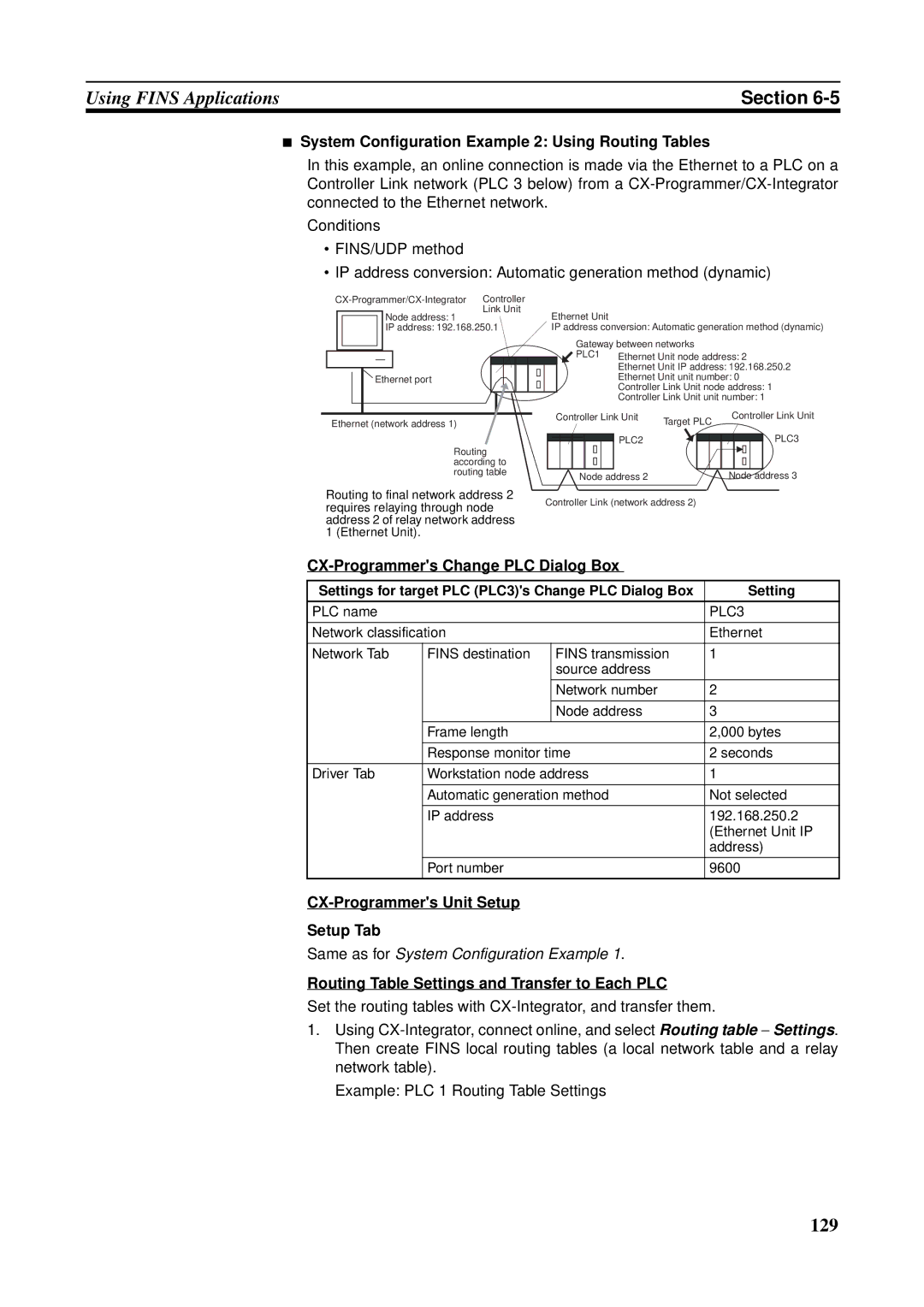
Settings for target PLC PLC3s Change PLC Dialog Box
System Configuration Example 2 Using Routing Tables
Routing Table Settings and Transfer to Each PLC
PLC3
FinsGateway
Overview of Setup Methods Starting FinsGateway Settings
Etnunit Driver Setup
Local Network Table
Network Tab
Communication Unit Tab
132
133
Starting FinsGateway Etnunit Service
Conditions
Not set. All defaults are used
Communications Specifications
CX-Programmers Unit Setup
Communicating between Omron PLCs
PLC Communications Data Areas
Area Range
SEND090
Using SEND090, RECV098, and CMND490
Ning word D at the remote destination node node address N
RECV098
CMND490
Hex 2 s Destination node number N To FE Hex
Commands Addressed to CS/CJ-series CPU Units
Usage Command Name Function Code
Writing Programs
Flag name Address Contents Word Bits
Communications Port Completion Codes
Communications Port Error Flag and Completion Codes CMND490
Word Contents
Timing of Communications Flag Changes
144
Program Example
146
CPU execution mode Processing time considerations
Transmission Delays
CPU Bus Unit Service Cycle Local Node
SEND090
CPU Bus Unit Service Cycle Remote Node
CPU Bus Unit Service Processing Time Local Node
Transmission Delay
Transmission Processing Time
Example Calculations
CPU Bus Unit Service Processing Time Remote Node
CPU processing mode Processing time considerations Settings
Calculation
Equation illustrated in the following diagram
RECV098
Reception processing time command
Transmission processing time command
Transmission Delay Command
Response
152
Conditions for High Traffic
Precautions on High Traffic in Fins Communications
Calculations
Avoiding Errors due to High Traffic
Fins Commands Addressed to Ethernet Units
Response Code List
Command Codes and Response Codes
Command Code List
Command code Name
Socket Applications
Format
Communications Type
Parameters
CIO
Command/Response Reference
Reset
FINS/UDP Port Number Setting
Broadcast Address Setting
IP Address Conversion Method Setting
Controller Data Read
Controller Status Read
IP Address Table Error
Error Flags Response
IP Address Error
IP Router Table Error
Internode Echo Test
Eeprom Error
Runs the echo test between specified nodes
Broadcast Test Results Read
Command Block Response Block Parameters
Test Data Command, Response
Broadcast Data Send
Reads the error log
Error LOG Read
Test Data Command
Bytes can be specified
Error Code, Detailed Information
Error LOG Clear
Error Log Data Response
Minute, Second, Day, Hour, Year, Month
Results Storage Format
UDP Open Request
Requests processing to open a socket
Requests that data be sent from a UDP socket
UDP Socket Number Command Results Storage Area Command
UDP Receive Request
Enobufs
Results Storage Area Response Codes
UDP Send Request
Requests that data be received by a UDP socket
170
UDP Close Request
Requests processing to close a socket
Passive TCP Open Request
Response code Description 0000 Normal
Remote IP address Remote TCP port Description
Econnaborted
Econnreset
Active TCP Open Request
Tunreach
175
Eacces
Drnotavail
TCP Receive Request
Requests that data be sent from a TCP socket
Requests that data be received at a TCP socket
TCP Send Request
Etimedout
Results Storage Format Parameters
Enetunreach
TCP Close Request
Ehostunreach
Ping
Destination IP Address Command Timeout Value Command
Response Block Parameters
FINS/TCP Connection Remote Node Change Request
Ping Command
Remarks
2232
FIFINS/TCP Connection No. Command Response
FINS/TCP Connection Status Read
Reads the FINS/TCP connection status
Remote TCP Port Number Response TCP Transitions Response
Number of Records Command
IP Address Table Write
Writes the IP address table
IP Address Write
Precautions Response Codes
IP Address Table Records Command
Fins Node Address
IP Address Table Read
Reads the IP address table
IP Router Table Read
Reads the IP router table
IP Network Address
Router IP Address
IP Status Response
Protocol Status Read
Reads the Ethernet Unit protocol status
Value
Type number Description
Connection Information 60 Bytes
Send Information 40 Bytes
Receive Information
Memory Status Read
Memory Status Response
Socket Status Read
Reads Fins node addresses and IP addresses
Address Information Read
TCP Transitions 4 bytes
Number of Addresses Response
IP address set on the Ethernet Unit hexadecimal
IP Address Read
Node address set on the Ethernet Unit hexadecimal
Fins Node Address Response
Subnet Mask Response
Troubleshooting
Troubleshooting with Indicators
Probably cause Correction
Error Status
Word = CIO 1500 + 25 x unit number +18
Logged Errors
Error Log
Following errors are recorded in the error log
Error Log Table
Error Log Error Codes
Error Log Location Fins Commands for Error Logs
204
205
206
207
208
Troubleshooting Procedures
Startup Problems
Fins Communications Problems SEND090/RECV098/ CMND490
Is the control data For the instruction set Incorrectly?
Problems
UDP Socket Problems
General Problems
Opening and Closing
Reception Problems
Read Controller Status
Transmission Problems
Is send Y processing not Finishing?
TCP Socket Problems
General Problems
Closing Problems
Opening Problems
Refer to General Problems on
216
FTP Service Problems
Connection Problems
File Transfer Problems
END
Network Connection Problems
Status Read
Mail Not being Sent
A R T
Mail Not being Received
A R T
Clock Not being Automatically Adjusted
Flashing? Status bit ON?
Controller
Troubleshooting with Response Codes
Main code Sub-code Check point Probable cause Remedy
Status Read
224
225
226
Codes stored in the Results Storage Area
Network Relay Errors
Results Storage Area Response Codes
Devices
Ealready
Eisconn
Enotconn
Emsgsize
Response Unix error Description Probable remedy Code
230
Ethernet Network Parameters
Parameter Value Description
Page
Buffer Configuration
Appendix B
Network Memory
TCP Status Transitions
Status Meaning
Page
Ascii Characters
Space
Page
Settings after Replacing a CPU
Maintenance
Settings after Replacing an Ethernet Unit
Replacing an Ethernet Unit
Page
Items
Inspections
Tools Required for Inspection
Page
Ethernet Unit Web Function
Unit Setup Functions
Web Function List
Appendix G
POP
Status Monitor
Web Function Password
Using the Web Function Setting Password
Menu item Corresponding CX-Programmer function
Appendix G
247
248
Numerics
Index
251
252
253
254
255
256
Revision History
Cat. No. W420-E1-04 Revision code
Revision History
Omron Corporation Control Devices Division H.Q
Regional Headquarters
Authorized Distributor