Section 5. Mechanical Adjustments
5.7 Timing Belt Tension Adjustment
STEP | PROCEDURE |
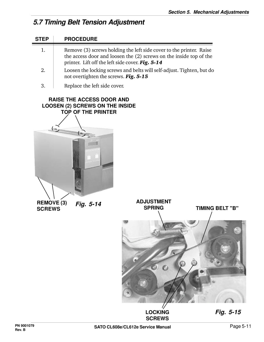
1.Remove (3) screws holding the left side cover to the printer. Raise the access door and loosen the (2) screws on the inside top of the printer. Lift off the left side cover. Fig.
2.Loosen the locking screws and belts will
3.Replace the left side cover.
RAISE THE ACCESS DOOR AND
LOOSEN (2) SCREWS ON THE INSIDE
TOP OF THE PRINTER
REMOVE (3) Fig. | ADJUSTMENT | TIMING BELT "B" |
SCREWS | SPRING |
LOCKING | Fig. |
SCREWS |
|
PN 9001079 | SATO CL608e/CL612e Service Manual | Page |
Rev. B |
|
|