Section 6. Replacement Procedures
6.9 Replacing the Ribbon Drive Clutch Washers
Both the ribbon unwind and the rewind drive spindles incorporate a friction clutch assembly to control tension. The friction washers within these clutch assemblies are replaceable. The procedure is identical for both the
DISASSEMBLE
STEP | PROCEDURE |
1.Switch the printer OFF and disconnect the power cable.
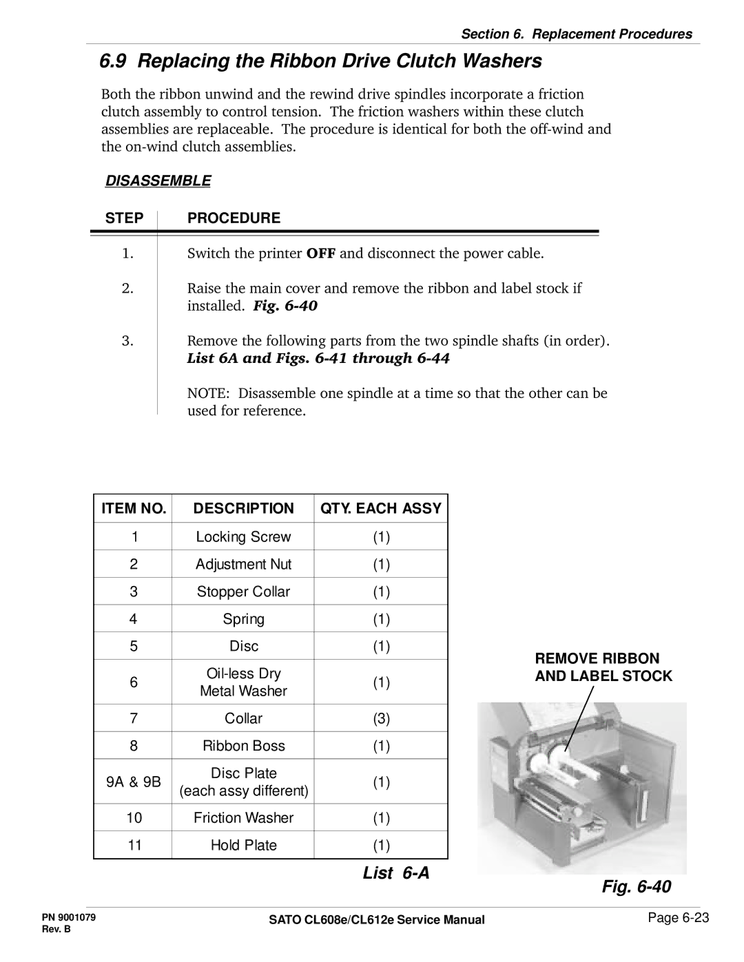
2.Raise the main cover and remove the ribbon and label stock if installed. Fig.
3.Remove the following parts from the two spindle shafts (in order). List 6A and Figs.
NOTE: Disassemble one spindle at a time so that the other can be used for reference.
ITEM NO. | DESCRIPTION | QTY. EACH ASSY |
|
|
|
|
|
1 | Locking Screw | (1) |
|
|
|
|
|
2 | Adjustment Nut | (1) |
|
|
|
|
|
3 | Stopper Collar | (1) |
|
|
|
|
|
4 | Spring | (1) |
|
|
|
|
|
5 | Disc | (1) | REMOVE RIBBON |
|
|
| |
|
| ||
6 | (1) | AND LABEL STOCK | |
Metal Washer |
| ||
|
|
| |
|
|
|
|
7 | Collar | (3) |
|
|
|
|
|
8 | Ribbon Boss | (1) |
|
|
|
|
|
9A & 9B | Disc Plate | (1) |
|
(each assy different) |
| ||
|
|
| |
|
|
|
|
10 | Friction Washer | (1) |
|
|
|
|
|
11 | Hold Plate | (1) |
|
|
|
|
|
|
| List | Fig. |
|
|
|
PN 9001079 | SATO CL608e/CL612e Service Manual | Page |
Rev. B |
|
|