Manuals
/
SATO
/
Computer Equipment
/
Printer
SATO
CL608e/CL612e
manual
Dispenser Assembly Option
Models:
CL608e/CL612e
1
231
245
245
Download
245 pages
38.96 Kb
228
229
230
231
232
233
234
235
Troubleshooting
Specification
Physical Characteristics
Install
Parts list
Test Point Chart
External Signal Interface
Default Settings
LCD Panel Configuration
Intermittent Problems
Page 231
Image 231
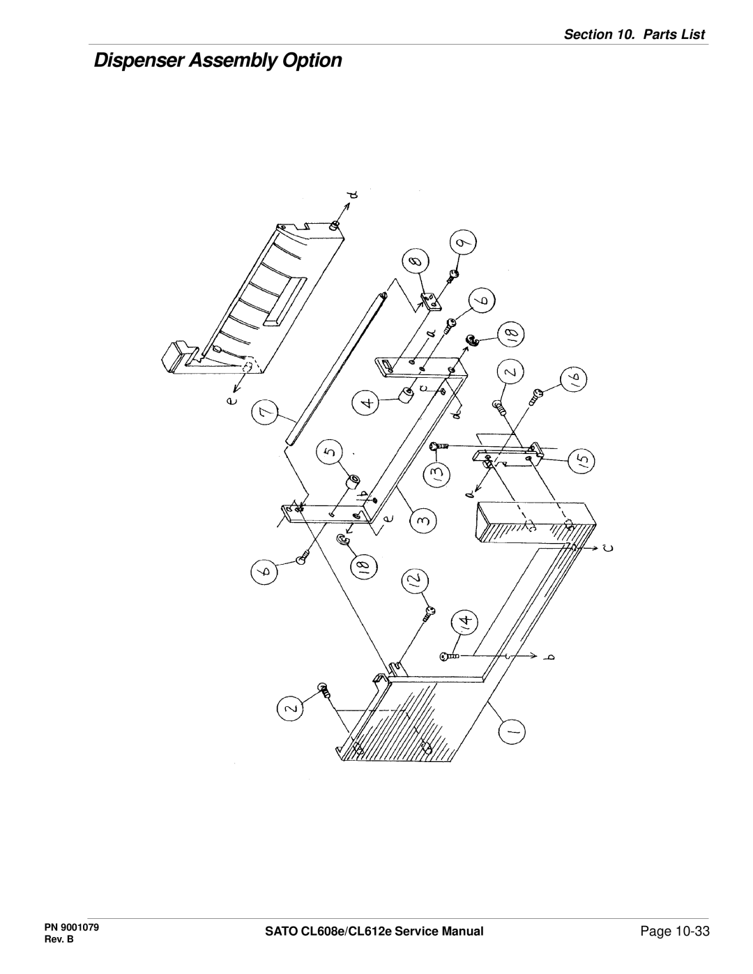
Section 10. Parts List
Dispenser Assembly Option
PN 9001079
SATO CL608e/CL612e Service Manual
Page
10-33
Rev. B
Page 230
Page 232
Page 231
Image 231
Page 230
Page 232
Contents
CL608e/CL612e Printers
PN 9001079 Rev. B
Table of Contents
Troubleshooting
Optional Accessories
PN 9001079 Rev. B
Overview
Section
Front Access Door
Physical Characteristics
Interface Slot
Printer Features
EXT Connector
Rear Panel
Refer to Section
Operation Panel/Displays
VR4 Display
Potentiometers
Components
Sensors and Switches
Switches and Sensors
Media Hold Down
EYE-MARK Sensor
Installation Considerations
Optional Accessories
Ribbon
Environment & Approvals
General Printer Specifications
General Printer Specifications
CPU
Character Fonts
Bar Codes
Specification CL608e CL612e
PN 9001079 Rev.B
DSW1
Dip Switch Settings
Setting
RS232 Transmit/Receive Setting located on RS232 I/F Module
DSW2
Printer Set up
DSW3
External Signal Interface
Setting DSW3
Dip Switch Selections
Default Settings
Mode KEY Sequence Initial Display
LCD Panel Configuration
000000
LCD Panel Normal Mode
Initializing Rom
QTY
Print Speed Adjustment
Pitch Offset Adjustment
Step Procedure
C D E F G
Cancel print job Yes no
Cancel print job
Cancel Print Job
Zero Slash
Initializing Advanced mode Rom
LCD Panel- Advanced Mode
Auto online
Print Offset
LCD Panel Advanced Mode
Print offset v+0000 H+000
Set calendar
Calendar 00/00/00
Ignore cr/lf
Ignore CR/LF
Character Pitch
Advanced Mode Card Mode
LCD Panel -Card Mode
Mem Select CC1
Card -MemoryCopy TrueTypeFont y/n
LCD Panel Card Mode
Mode
Card -MemoryCopy SATOFont y/n
Copy start Yes no
LCD Panel Card
Card memory Copying
Card -MemoryCopy All y/n
Memory- card copy copying
Memory -cardCopy All
Card -memoryCopy Program y/n
Card- memory copy copying
Card-Memory Copy Program Y/N
Program Y/N
Memory-Card Copy
Card format Yes no
Memory format Yes no
Card Format Yes No
Gap X.XV Input
Service mode
LCD Panel Service Mode
Gap x.xv input
Gap x.xv input
Eye Input
Eye x.xv input
Auto Online Feed Yes No
Feed on error yes no
Auto online feed yes no
Reprint w/feed yes no
EXt pin9 Select Mode Mode2
Forward/backfeed distance default
Select LCD Display Language
Euro code d5
Ignore can/dle Yes no
Ribbon near end Enable disable
Priority Setting LCD Command
Service Mode
Head Count clear Yes no
Counters mode
LCD Panel Counters Mode
Counters Hd dsp cut life
Test Print Mode
Test print mode configuration
Test print Size
Default setting Yes no
LCD Panel Test Print Mode
Default Setting Mode
Counter clear all
Factory mode
Initializing
DiPSw2-4 on-off
All clear Counter eeprom
All clear mode
Counter all clear All clear mode Completed
LCD Panel Maintenance Mode All Clear Mode
User download Waiting
LCD Panel Clear Non-Standard Protocol
Download User Defined Protocol Codes
User Download Press the Line Key Countinued
Hex Dump Mode
Initializing Rom Online Qty000000
LCD Panel Download User Defined Protocol Codes
Initializing Flash download
LCD Panel -Firmware Download Mode
Configuration
Sample Test Labels
Memory Head Check Factory
Interface Types
Interface Specifications
USB Interface Ethernet
Multi Job Buffer
Receive Buffer
Data Streams
Ieee 1284 Parallel Interface
PIN Assignments Ieee 1284 Cable END
PIN Signal Direction
General Specifications
Electrical Specifications
RS232C Serial Interface
Printer
Cable Requirements
DB9
Host Interconnection
Signal Description
Ready/Busy Flow Control
PIN
On/X-Off Flow Control
Universal Serial Bus USB Interface
Bi-Directional Communications
Ethernet Interface
Pin Assignments
Accessory EXT Connector
Standard Operation
Repeat Print
Error Signals
Interface Specifications
Electrical Checks and Adjustments
Steps Prior to Some Procedures
DC Power Voltage Checks
Power Supply Main PCB Interface Board VR2 DEM
Test Point Connector
Receptacle on
Connector Nibs on
Connect TP Test Module to PCB Test Point @
Main PCB TP Test Module To PCB Test Point @ CN13
Test Point Chart
Potentiometer Assignments & Adjustments
Power Supply Main PCB Interface Board VR2 DEM VR3 CE
Test print size 10cm
5a Print Position Adjustment
Test print Press the feed key
5b Print Position Adjustment
Label Gap Adjustment
Eye-Mark Adjustment
Offset Label Stop Position Adjustment
Ribbon Sensor Operation Verification
Place DSW2-1 OFF Position Step Procedure
Initializing Online
Ribbon end
Ribbon Sensor Adjustment
LCD Display Adjustment
Print darkness 1L 2M 3D
Print Darkness Adjustment
Mechanical Adjustments
Remove Ribbon Label Stock
Ribbon Clutch Adjustments
Rewind
Unwind
Empty Ribbon Cores
Ribbon Rewind Clutch Adjustment
Print Head Position Adjustment
Rotation of Allen Movement of Print Head Wrench
Allen Wrench Adjust Screws
Measure from
Measure from Bottom of Barcode To Bottom of Label
Adjust Plate Locking Screws Eccentric
Print Head Balance Adjustment
Turn Eccentric Loosen Locking Screws
Ribbon Roller Adjustment
Feed Roller Adjustment Label Tracking
Pull Media LID
Adjust Plate
Screws Spring Locking
Timing Belt Tension Adjustment
Latched Position Unlatched
Head Latch Adjustment
NOTCH/GAP Locations Maximum & Minimum
Notch/Gap Sensor Adjustment
NOTCH/GAP Sensor Adjustment Range
Minimum INTER-LABEL
Mechanical Adjustments
Replacement Procedures
Replacing the Main Circuit Board
Figs
Remove Screw
Disconnect Cables Remove 2 Screws
Press Outward Memory Module PCB Main PCB Memory Frame
Replacing the Main Circuit Board
Back of Printer Fuse Under Cover
Replacing the Fuses
Fuses Main PC Board
Replacing the Power Supply
To Detach Main
Power Supply Remove 2 Screws
Lift OUT Power
Lower Media Holder Remove Bottom TOP Screws
Detach Connector From Circuit Board
Replacing the Stepper Motor
Remove
Remove the Ribbon and Label Stock
Replacing the Timing Belts
Rear Tension Platen Adjustment Roller
Bearing Do not Disturb These TWO Screws
Replacing the Print Head
Remove Ribbon Label Stock Stud Screws
Replacing the Print Head
Replacing the Platen
To Release Belt Tension
CL608 Platen Side CL612 Platen
Loosen 2 SET Screws Remove Pulley From END of Shaft
Spring END Must Not be Under Bushing Plate
Showing
Holding Clamp Bushing Plate
Position
Replacing the Ribbon Drive Clutch Washers
List 6-A
Item no Description QTY. Each Assy
List 6A
Order see Item
Assemble
Item 11 Teeth Facing Outward to Engage Item 10 Felt Washer
With 2 Screws
Item 6 OIL-LESS
Replacing the Ribbon Motion Sensor
Alignment PIN Remove Screw
Replacing the Ribbon Motion Sensor
Sensor Locations
Step
Detach the Ramp Plate
Bottom
Replacing the Top Half of the Notch/Gap Sensor
NOTCH/GAP Sensor
Remove Screws
Replacing the Display Panel or Keyboard
Raise Access Door Display Panel Cover
To Frame Remove Screws
Display Panel Assembly Dispenser Cover Platen Remove 1 Screw
Display Panel Assembly Remove Screw
Replacement Procedures
Section
Small large
Factory Settings/Test Print
Clear Head Counters
Factory mode
Clear Dispenser Counter
Counter clear Dis
Clear Cutter Counter
Counter clear cut
Clear Eeprom
Counter all clear completed All clear mode
Large Test Print Small Test Print
Sample Test Prints
Factory Resets
Troubleshooting
IEEE1284 Parallel Interface
Initial Check List
IEEE1284 Parallel Interface
Universal Serial BUS USB
Lan Ethernet Interface
Installation Problems Printer Does Not Come Up Ready
Intermittent Problems
NetWare Troubleshooting
Windows NT/LAN Server Troubleshooting
Windows NT/LAN Server Troubleshooting
LED
Error Signals
Print Quality Problems
Troubleshooting Tables
Print Quality Problems
Error LED
Print Quality Problems
Factory Default
Head Pattern Examples
Poor Head
Head Pattern Examples
Hex Dump Diagnostic Labels
Print Buffer Hex Dump
Receive Buffer Hex Dump
Troubleshooting
Optional Accessories
Label Cutter Kit Installation
Remove Screws AT 5 Places to Detach Front Cover
Remove 3 Screws Front Cover
Cuts
Cutter Unit Remove
Secure Cutter with Screws AT 5 Places
Cutter
Components as Supplied in Kit
Label Dispenser Installation
Label Dispenser Installation Components as Supplied in Kit
Figs
Label Dispenser Installation
Remove
By Motor
Place Spring on PIN Both Ends
Right Side Frame
Into Position
Opposite Side
Secure Bracket
To Wall from
Right
Label Dispenser Installation
Ref. -8h
Front Printer Dispenser Unit in Open Position
Approximate Position
Slot for Memory Card
Pcmcia Memory Expansion Installation
RECEIVED. Standoffs will
Mount Memory Board to
Step
Step
22SECURE from Underside of Main PCB Board with
Memory PCB Board Main PCB
Notches
Flash Memory Expansion Installation
Press Outward
Indexing
Flash Memory Expansion Installation
Real Time Clock Installation
Real Time Clock Chip Installation
Factory Reset Procedure
Set Calendar
Yes
Rev. B
Optional Accessories
Spare Parts List
Base Cover Assembly
Base Cover Assembly
Base Cover Assembly
Base Cover Assembly
Base Cover Assembly
Code Description
Code Description QTY
Base Cover Assembly
PN 9001079 Rev. B
Frame Assembly
Frame Assembly
Frame Assembly
Frame Assembly
Code Description
Code Description QTY
Frame Assembly
Print Head Assembly
Print Head Assembly
Code Description QTY
Code Description
Ribbon Assembly
Ribbon Assembly
Ribbon Assembly
Code Description QTY
Code Description
Feed Roller Assembly
Feed Roller Assembly
Code Description QTY
Main PCB Assembly
Interface Option
Dispenser Assembly Option
Dispenser Assembly Option
Dispenser Assembly Option
Dispenser Assembly Option
Code Description
Dispenser Assembly Option
Dispenser Assembly Option
Cutter Assembly Option
Cutter Assembly Option
Code Description QTY
Cutter Assembly Option
Pcmcia Memory Option
Parts List
Index
Index-2
Index-3
Top
Page
Image
Contents