Section 6. Replacement Procedures
6.10 Replacing the Ribbon Motion Sensor
The Ribbon Motion Sensor is easily replaced for service.
STEP | PROCEDURE |
1.Switch the printer OFF and disconnect the power cable.
2.Remove (3) screws holding the left side cover to the printer. Raise the access door and loosen the (2) screws on the inside top of the printer. Lift off the left side cover to expose the main PCB. Refer to Section
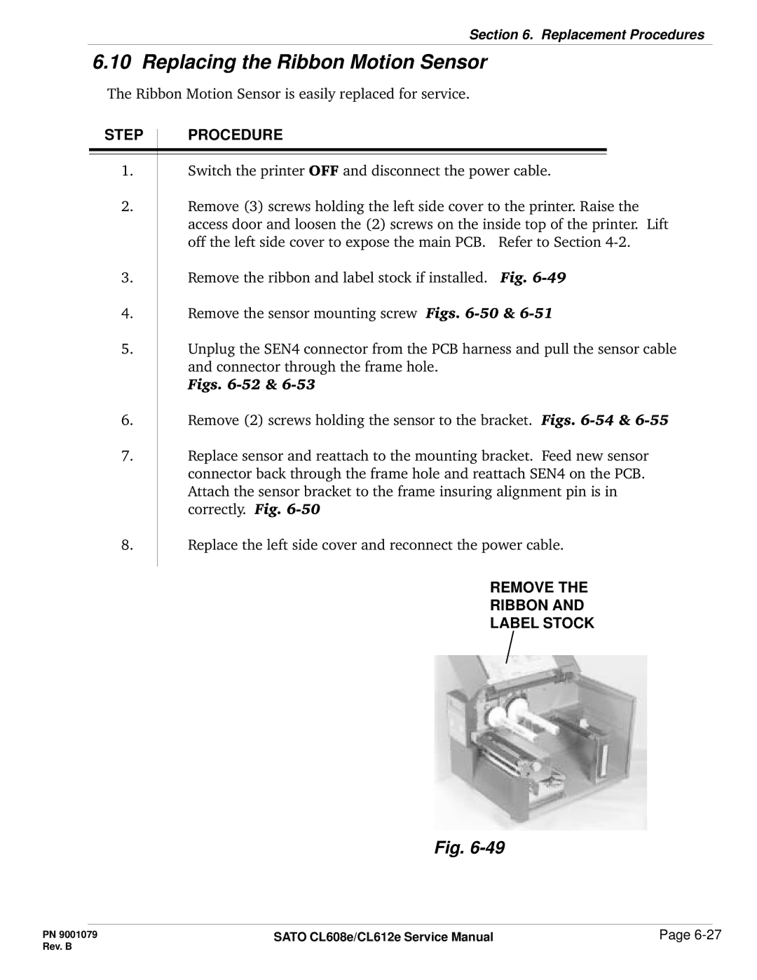
3.Remove the ribbon and label stock if installed. Fig.
4.Remove the sensor mounting screw Figs.
5.Unplug the SEN4 connector from the PCB harness and pull the sensor cable and connector through the frame hole.
Figs.
6.Remove (2) screws holding the sensor to the bracket. Figs.
7.Replace sensor and reattach to the mounting bracket. Feed new sensor connector back through the frame hole and reattach SEN4 on the PCB. Attach the sensor bracket to the frame insuring alignment pin is in correctly. Fig.
8.
Replace the left side cover and reconnect the power cable.
REMOVE THE
RIBBON AND
LABEL STOCK
Fig.
PN 9001079 | SATO CL608e/CL612e Service Manual | Page |
Rev. B |
|
|
