Section 9. Optional Accessories
9.6 Real Time Clock Installation
The Real Time Clock Chip allows the date and time to be maintained in the local printer rather than using the system clock. It consists of a special clock chip that replaces the EEPROM chip on the main PCB.
STEP | PROCEDURE |
1.Switch the printer OFF and disconnect the power cable.
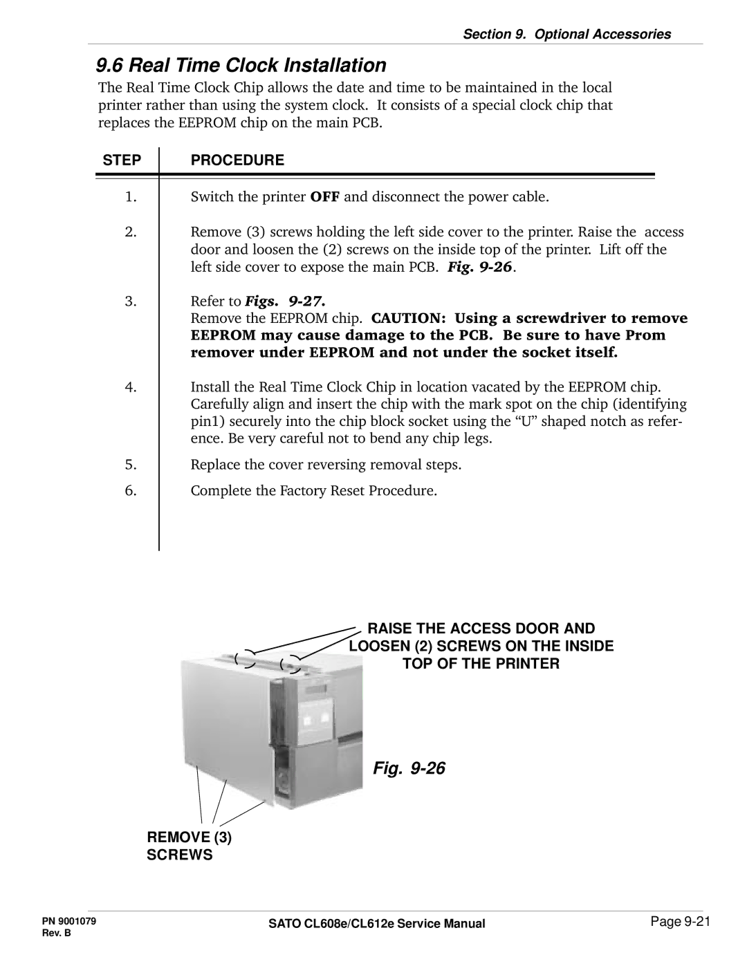
2.Remove (3) screws holding the left side cover to the printer. Raise the access door and loosen the (2) screws on the inside top of the printer. Lift off the left side cover to expose the main PCB. Fig.
3.Refer to Figs.
Remove the EEPROM chip. CAUTION: Using a screwdriver to remove EEPROM may cause damage to the PCB. Be sure to have Prom remover under EEPROM and not under the socket itself.
4.Install the Real Time Clock Chip in location vacated by the EEPROM chip. Carefully align and insert the chip with the mark spot on the chip (identifying pin1) securely into the chip block socket using the “U” shaped notch as refer- ence. Be very careful not to bend any chip legs.
5.Replace the cover reversing removal steps.
6.Complete the Factory Reset Procedure.
RAISE THE ACCESS DOOR AND
LOOSEN (2) SCREWS ON THE INSIDE
TOP OF THE PRINTER
Fig.
REMOVE (3)
SCREWS
PN 9001079 | SATO CL608e/CL612e Service Manual | Page |
Rev. B |
|
|