Section 9. Optional Accessories
Label Dispenser Installation
STEP PROCEDURE
15.Refer to Fig.
Install dispenser unit in its entirety to the front of the print cover previously removed in Step 6 with (5) screws.
16.Refer to Fig.
Install cable stay in the approximate position shown in Figs.
17.Disengage dispenser front door by grasping cut out section and lifting up and forward.
18.Place
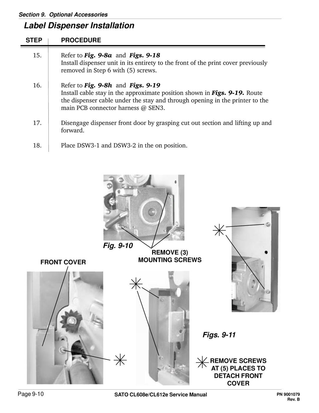
Fig.
| REMOVE (3) |
FRONT COVER | MOUNTING SCREWS |
|
Figs. 9-11
REMOVE SCREWS
AT (5) PLACES TO
DETACH FRONT
COVER
Page | SATO CL608e/CL612e Service Manual |