Section 4. Electric Checks and Adjustments
4.5a Print Position Adjustment
Print Postition is adjusted with the VR3(PITCH) potentiometer on the Front Panel and/or VR1 potentiometer on the main PCB board.
The following instructions are for adjusting the potentiometer on the Front Panel. Refer to Section 4.5b for making adjustments using the potentiometer on the PCB board.
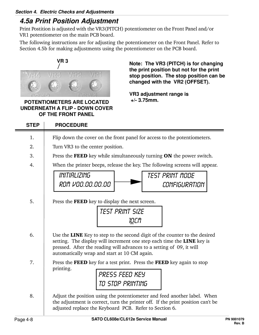
VR 3
POTENTIOMETERS ARE LOCATED UNDERNEATH A FLIP - DOWN COVER OF THE FRONT PANEL
Note: The VR3 (PITCH) is for changing the print position but not for the print stop position. The stop position can be changed with the VR2 (OFFSET).
VR3 adjustment range is +/- 3.75mm.
STEP PROCEDURE
1.Flip down the cover on the front panel for access to the potentiometers.
2.Turn VR3 to the center position.
3.Press the FEED key while simultaneously turning ON the power switch.
4.When the printer beeps, release the key The following screens will appear.
initializing
rom v00.00.00.00
test print mode configuration
5.Press the FEED key to display the next screen.
test print size 10cm
6.Use the LINE Key to step to the second digit of the counter to the desired setting. The display will increment one step each time the LINE key is pressed. After the reading will advances to a setting of 09, it will automatically wrap and start at 10 CM again.
7.Press the FEED key for a test print. Press the FEED key again to stop printing.
press feed key to stop printing
8.Adjust the position using the potentiometer and feed another label. When the adjustment is correct, turn the printer off. If the print position can't be adjusted replace the Keyboard PCB. Refer to Section 6.
Page | SATO CL608e/CL612e Service Manual |