Section 6. Replacement Procedures
6.8 Replacing the Platen
STEP | PROCEDURE |
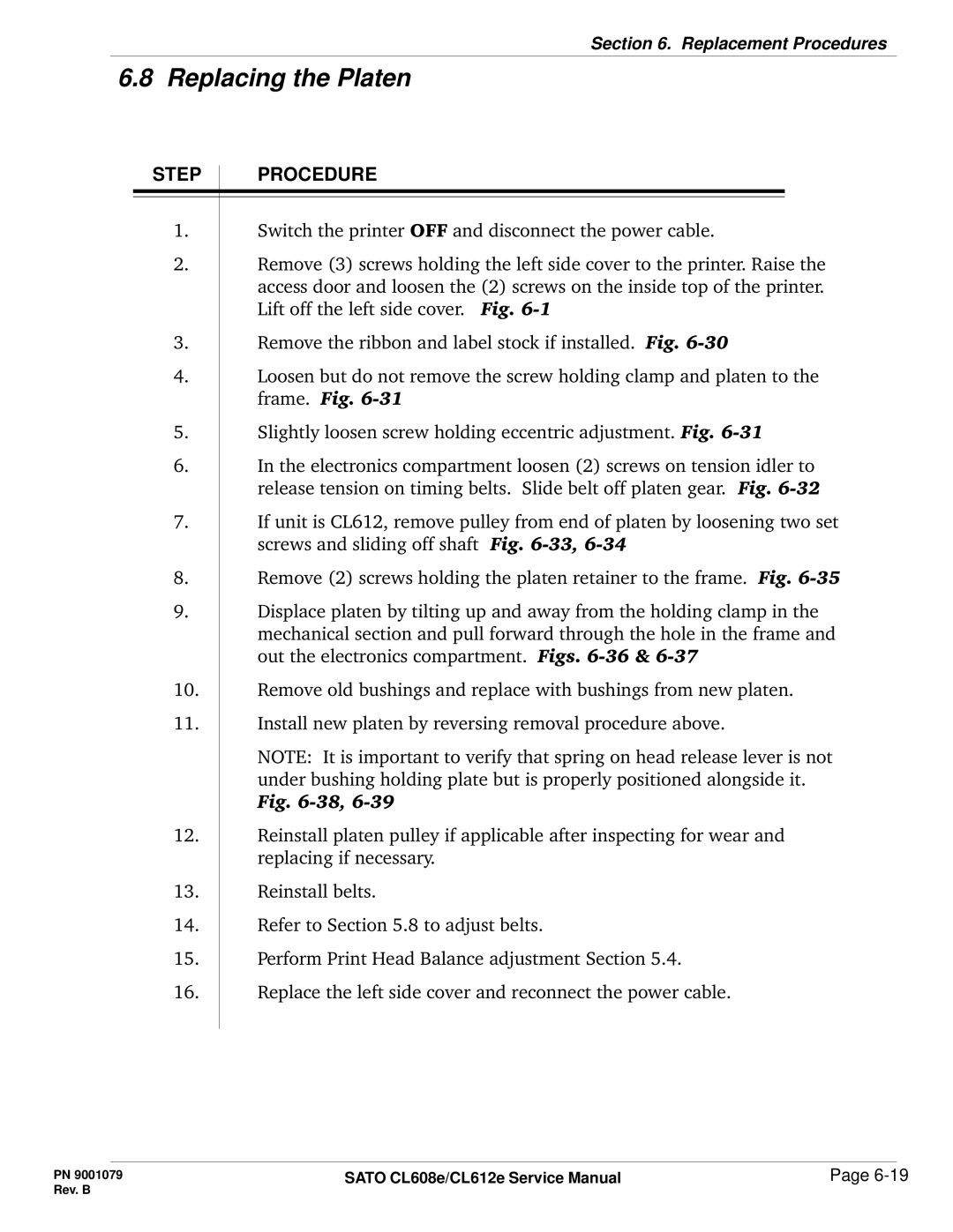
1.Switch the printer OFF and disconnect the power cable.
2.Remove (3) screws holding the left side cover to the printer. Raise the access door and loosen the (2) screws on the inside top of the printer. Lift off the left side cover. Fig.
3.Remove the ribbon and label stock if installed. Fig.
4.Loosen but do not remove the screw holding clamp and platen to the frame. Fig.
5.Slightly loosen screw holding eccentric adjustment. Fig.
6.In the electronics compartment loosen (2) screws on tension idler to release tension on timing belts. Slide belt off platen gear. Fig.
7.If unit is CL612, remove pulley from end of platen by loosening two set screws and sliding off shaft Fig.
8.Remove (2) screws holding the platen retainer to the frame. Fig.
9.Displace platen by tilting up and away from the holding clamp in the mechanical section and pull forward through the hole in the frame and out the electronics compartment. Figs.
10.Remove old bushings and replace with bushings from new platen.
11.Install new platen by reversing removal procedure above.
NOTE: It is important to verify that spring on head release lever is not under bushing holding plate but is properly positioned alongside it. Fig.
12.Reinstall platen pulley if applicable after inspecting for wear and replacing if necessary.
13.Reinstall belts.
14.Refer to Section 5.8 to adjust belts.
15.Perform Print Head Balance adjustment Section 5.4.
16.Replace the left side cover and reconnect the power cable.
PN 9001079 | SATO CL608e/CL612e Service Manual | Page |
Rev. B |
|
|
