Section 6. Replacement Procedures
Replacing the Main Circuit Board
STEP | PROCEDURE |
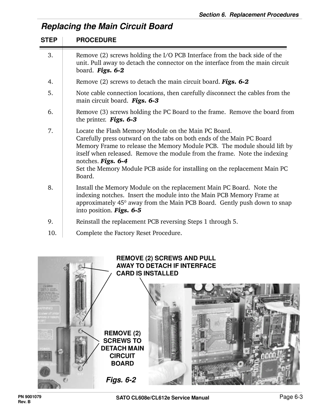
3.Remove (2) screws holding the I/O PCB Interface from the back side of the unit. Pull away to detach the connector on the interface from the main circuit board. Figs.
4.Remove (2) screws to detach the main circuit board. Figs.
5.Note cable connection locations, then carefully disconnect the cables from the main circuit board. Figs.
6.Remove (3) screws holding the PC Board to the frame. Remove the board from the printer. Figs.
7.Locate the Flash Memory Module on the Main PC Board.
Carefully press outward on the tabs on both ends of the Main PC Board Memory Frame to release the Memory Module PCB. The module should lift by itself when released. Remove the module from the frame. Note the indexing notches. Figs.
Set the Memory Module PCB aside for installing on the replacement Main PC Board.
8.Install the Memory Module on the replacement Main PC Board. Note the indexing notches. Insert the module into the Main PCB Memory Frame at approximately 450 away from the Main PCB Board. Gently push down to snap into position. Figs.
9.Reinstall the replacement PCB reversing Steps 1 through 5.
10.Complete the Factory Reset Procedure.
REMOVE (2) SCREWS AND PULL
AWAY TO DETACH IF INTERFACE
CARD IS INSTALLED
REMOVE (2)
SCREWS TO
DETACH MAIN
CIRCUIT
BOARD
Figs. 6-2
PN 9001079 | SATO CL608e/CL612e Service Manual | Page |
Rev. B |
|
|