|
|
|
| Isolated Analog Programming Mode (ISOL) |
|
|
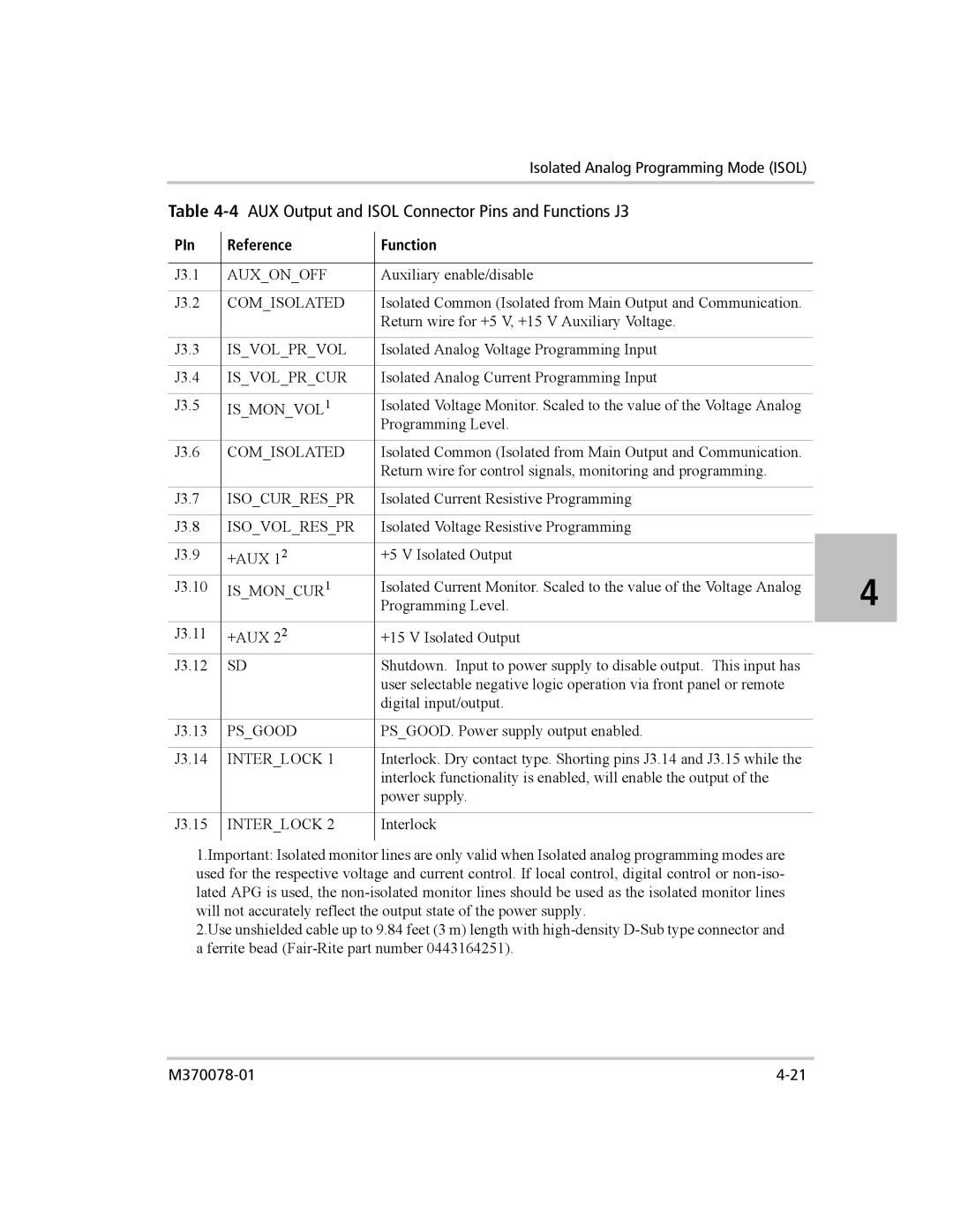
Table |
|
| ||||
PIn |
| Reference |
| Function |
|
|
|
|
|
| |||
|
|
|
|
|
|
|
J3.1 |
| AUX_ON_OFF |
| Auxiliary enable/disable |
|
|
|
|
|
|
|
|
|
J3.2 |
| COM_ISOLATED |
| Isolated Common (Isolated from Main Output and Communication. |
|
|
|
|
|
| Return wire for +5 V, +15 V Auxiliary Voltage. |
|
|
|
|
|
|
|
|
|
J3.3 |
| IS_VOL_PR_VOL |
| Isolated Analog Voltage Programming Input |
|
|
|
|
|
|
|
|
|
J3.4 |
| IS_VOL_PR_CUR |
| Isolated Analog Current Programming Input |
|
|
|
|
|
|
|
|
|
J3.5 |
| IS_MON_VOL1 |
| Isolated Voltage Monitor. Scaled to the value of the Voltage Analog |
|
|
|
|
|
| Programming Level. |
|
|
J3.6 |
| COM_ISOLATED |
| Isolated Common (Isolated from Main Output and Communication. |
|
|
|
|
|
| Return wire for control signals, monitoring and programming. |
|
|
|
|
|
|
|
|
|
J3.7 |
| ISO_CUR_RES_PR |
| Isolated Current Resistive Programming |
|
|
|
|
|
|
|
|
|
J3.8 |
| ISO_VOL_RES_PR |
| Isolated Voltage Resistive Programming |
|
|
|
|
|
|
|
|
|
J3.9 |
| +AUX 12 |
| +5 V Isolated Output |
|
|
|
|
|
|
|
| 4 |
J3.10 |
| IS_MON_CUR1 |
| Isolated Current Monitor. Scaled to the value of the Voltage Analog |
| |
|
|
|
| Programming Level. |
| |
J3.11 |
| +AUX 22 |
| +15 V Isolated Output |
|
|
J3.12 |
| SD |
| Shutdown. Input to power supply to disable output. This input has |
|
|
|
|
|
| user selectable negative logic operation via front panel or remote |
|
|
|
|
|
| digital input/output. |
|
|
|
|
|
|
|
|
|
J3.13 |
| PS_GOOD |
| PS_GOOD. Power supply output enabled. |
|
|
|
|
|
|
|
|
|
J3.14 |
| INTER_LOCK 1 |
| Interlock. Dry contact type. Shorting pins J3.14 and J3.15 while the |
|
|
|
|
|
| interlock functionality is enabled, will enable the output of the |
|
|
|
|
|
| power supply. |
|
|
|
|
|
|
|
|
|
J3.15 |
| INTER_LOCK 2 |
| Interlock |
|
|
|
|
|
|
|
|
|
1.Important: Isolated monitor lines are only valid when Isolated analog programming modes are used for the respective voltage and current control. If local control, digital control or
2.Use unshielded cable up to 9.84 feet (3 m) length with