Alarms and Errors
Alarm Masking
It is possible to completely disable some alarms through the use of the alarm mask. If an alarm is masked then this masking will prevent it from registering in the SCPI conditions registers as well as not triggering the alarm. The alarms that can be masked are identified in Table
For Example: |
|
If you wanted to enable the OTP, Foldback and UVP alarms you |
|
would take the OTP value of 2 and add it to the foldback value of 256 |
|
and the UVP value of 1024 to get a mask of 1282. This is the value |
|
you would send with the SCPI command. | 3 |
Control of the alarm mask is only available using the SCPI command. |
The SCPI command (s) for these instructions are:
[:]SYSTem[<channel>]:PROTection:MASK
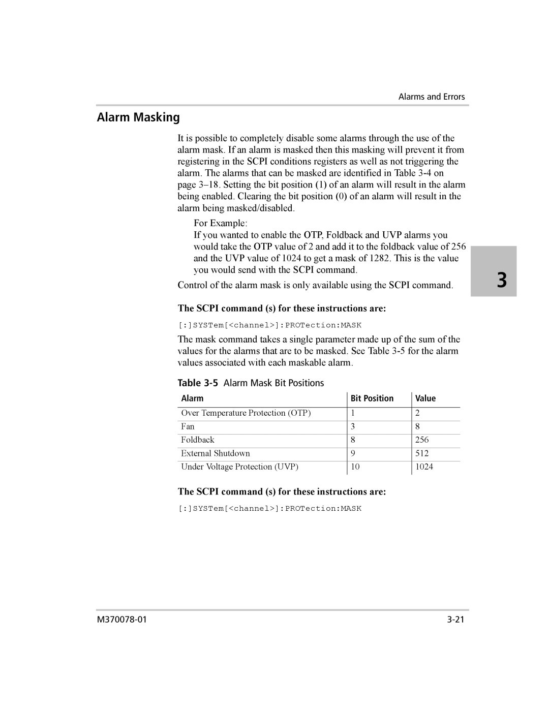
The mask command takes a single parameter made up of the sum of the values for the alarms that are to be masked. See Table
Table 3-5 Alarm Mask Bit Positions
Alarm | Bit Position | Value |
|
|
|
Over Temperature Protection (OTP) | 1 | 2 |
Fan | 3 | 8 |
Foldback | 8 | 256 |
External Shutdown | 9 | 512 |
Under Voltage Protection (UVP) | 10 | 1024 |
|
|
|
The SCPI command (s) for these instructions are: [:]SYSTem[<channel>]:PROTection:MASK
