Remote Operation
RS-485 Communication Cable with Two RJ-45s
Use the top connector of the two
Table |
|
|
|
| |||||
Pin |
| Name |
| Description |
|
| |||
|
|
|
| ||||||
|
|
|
|
|
|
|
|
|
|
1, 2 |
|
|
| NC |
| No connection |
|
| |
3 |
|
|
| RXD+ |
| Receive data | Twisted |
| |
|
|
|
|
|
|
|
| pair |
|
4 |
|
|
| RXD– |
| Receive data |
| ||
5 |
|
|
| TXD+ |
| Transmit data | Twisted |
| |
|
|
|
|
|
|
|
| pair |
|
6 |
|
|
| TXD– |
| Transmit data |
| ||
7 |
|
|
| GND |
| Ground |
|
| |
8 |
|
|
| NC |
| No connection |
|
| |
|
|
|
|
|
|
|
|
|
|
|
|
|
|
|
|
|
|
|
|
|
|
|
|
|
|
|
|
|
|
|
|
|
|
|
|
|
|
|
|
|
|
|
|
|
|
|
|
|
|
|
|
|
|
|
|
|
|
|
|
|
|
|
|
|
|
|
|
|
|
|
|
|
|
|
|
|
|
|
|
|
|
|
|
|
|
|
|
|
|
|
|
|
|
|
|
|
|
|
|
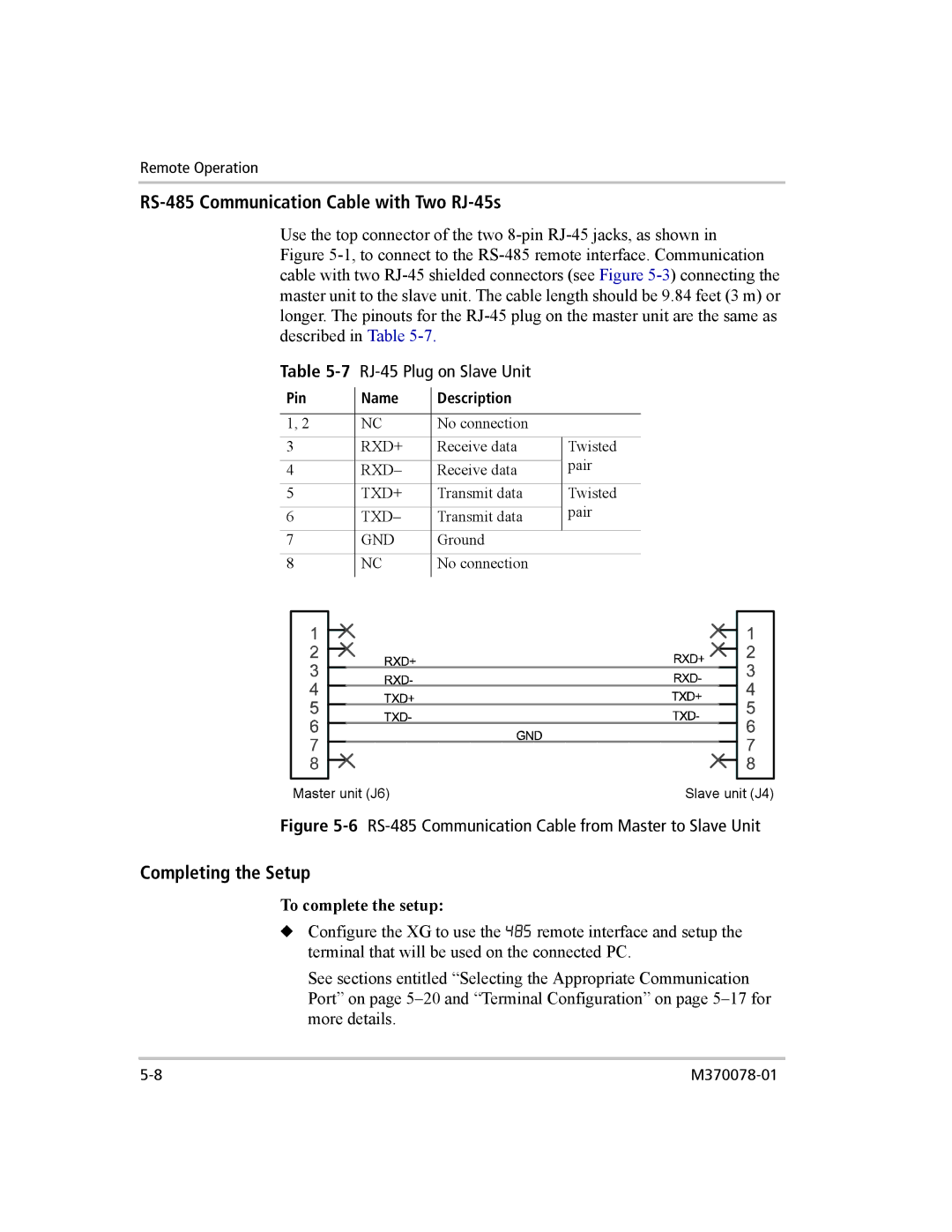
Master unit (J6) | Slave unit (J4) |
Figure 5-6 RS-485 Communication Cable from Master to Slave Unit
Completing the Setup
To complete the setup:
◆Configure the XG to use the 485 remote interface and setup the terminal that will be used on the connected PC.
See sections entitled “Selecting the Appropriate Communication Port” on page