Contents

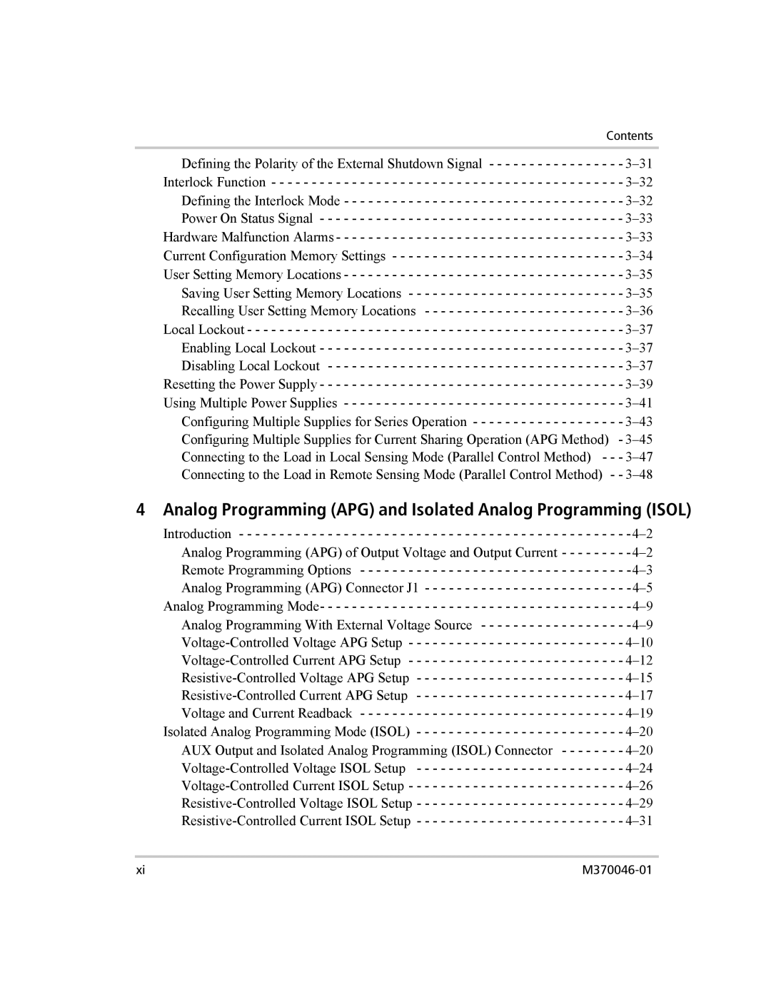
Defining the Polarity of the External Shutdown Signal - - - - - - - - - - - - - - - - - 3–31 Interlock Function - - - - - - - - - - - - - - - - - - - - - - - - - - - - - - - - - - - - - - - - - - - - 3–32 Defining the Interlock Mode - - - - - - - - - - - - - - - - - - - - - - - - - - - - - - - - - - - 3–32 Power On Status Signal - - - - - - - - - - - - - - - - - - - - - - - - - - - - - - - - - - - - - - 3–33 Hardware Malfunction Alarms - - - - - - - - - - - - - - - - - - - - - - - - - - - - - - - - - - - - 3–33 Current Configuration Memory Settings - - - - - - - - - - - - - - - - - - - - - - - - - - - - - 3–34 User Setting Memory Locations - - - - - - - - - - - - - - - - - - - - - - - - - - - - - - - - - - - 3–35 Saving User Setting Memory Locations - - - - - - - - - - - - - - - - - - - - - - - - - - - 3–35Recalling User Setting Memory Locations - - - - - - - - - - - - - - - - - - - - - - - - - 3–36 Local Lockout - - - - - - - - - - - - - - - - - - - - - - - - - - - - - - - - - - - - - - - - - - - - - - - 3–37 Enabling Local Lockout - - - - - - - - - - - - - - - - - - - - - - - - - - - - - - - - - - - - - - 3–37 Disabling Local Lockout - - - - - - - - - - - - - - - - - - - - - - - - - - - - - - - - - - - - - 3–37 Resetting the Power Supply - - - - - - - - - - - - - - - - - - - - - - - - - - - - - - - - - - - - - - 3–39Using Multiple Power Supplies - - - - - - - - - - - - - - - - - - - - - - - - - - - - - - - - - - - 3–41Configuring Multiple Supplies for Series Operation - - - - - - - - - - - - - - - - - - - 3–43 Configuring Multiple Supplies for Current Sharing Operation (APG Method) - 3–45Connecting to the Load in Local Sensing Mode (Parallel Control Method) - - - 3–47 Connecting to the Load in Remote Sensing Mode (Parallel Control Method) - - 3–48

4 Analog Programming (APG) and Isolated Analog Programming (ISOL)

Introduction - - - - - - - - - - - - - - - - - - - - - - - - - - - - - - - - - - - - - - - - - - - - - - - - -4–2

Analog Programming (APG) of Output Voltage and Output Current - - - - - - - - -4–2

Remote Programming Options - - - - - - - - - - - - - - - - - - - - - - - - - - - - - - - - - -4–3

Analog Programming (APG) Connector J1 - - - - - - - - - - - - - - - - - - - - - - - - - -4–5

Analog Programming Mode- - - - - - - - - - - - - - - - - - - - - - - - - - - - - - - - - - - - - - -4–9

Analog Programming With External Voltage Source - - - - - - - - - - - - - - - - - - -4–9

Voltage-Controlled Voltage APG Setup - - - - - - - - - - - - - - - - - - - - - - - - - - - 4–10

Voltage-Controlled Current APG Setup - - - - - - - - - - - - - - - - - - - - - - - - - - - 4–12

Resistive-Controlled Voltage APG Setup - - - - - - - - - - - - - - - - - - - - - - - - - - 4–15

Resistive-Controlled Current APG Setup - - - - - - - - - - - - - - - - - - - - - - - - - - 4–17

Voltage and Current Readback - - - - - - - - - - - - - - - - - - - - - - - - - - - - - - - - - 4–19

Isolated Analog Programming Mode (ISOL) - - - - - - - - - - - - - - - - - - - - - - - - - - 4–20

AUX Output and Isolated Analog Programming (ISOL) Connector - - - - - - - - 4–20

Voltage-Controlled Voltage ISOL Setup - - - - - - - - - - - - - - - - - - - - - - - - - - 4–24

Voltage-Controlled Current ISOL Setup - - - - - - - - - - - - - - - - - - - - - - - - - - - 4–26

Resistive-Controlled Voltage ISOL Setup - - - - - - - - - - - - - - - - - - - - - - - - - - 4–29

Resistive-Controlled Current ISOL Setup - - - - - - - - - - - - - - - - - - - - - - - - - - 4–31

xi

M370046-01

Page 13
Image 13
Xantrex Technology XG 850 manual Analog Programming APG and Isolated Analog Programming Isol