Step 6: Connecting Loads
Inductive Loads and Batteries
| CAUTION | |||
| The XG power supply requires freewheeling and blocking diodes across the | |||
| output while driving inductive loads or batteries to protect the power supply from |
| ||
|
| |||
| damage caused by power being fed back into the supply and from high voltage |
| ||
| transients. | 2 | ||
|
|
| ||
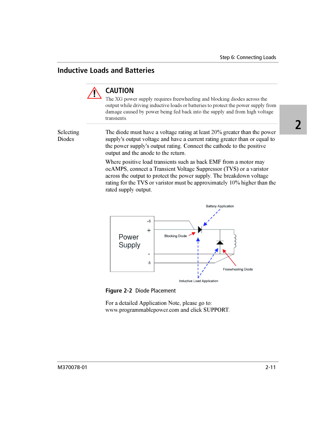
Selecting | The diode must have a voltage rating at least 20% greater than the power | |||
| ||||
Diodes | supply's output voltage and have a current rating greater than or equal to | |||
| the power supply's output rating. Connect the cathode to the positive | |||
| output and the anode to the return. | |||
Where positive load transients such as back EMF from a motor may ocAMPS, connect a Transient Voltage Suppressor (TVS) or a varistor across the output to protect the power supply. The breakdown voltage rating for the TVS or varistor must be approximately 10% higher than the rated supply output.
Figure 2-2 Diode Placement
For a detailed Application Note, please go to:
www.programmablepower.com and click SUPPORT.