Local Memory Bus (LMB) Interface Description
R
Read and Write Data Steering
The MicroBlaze
•byte, halfword, and word transfers to word devices
•byte and halfword transfers to halfword devices
•byte transfers to byte devices
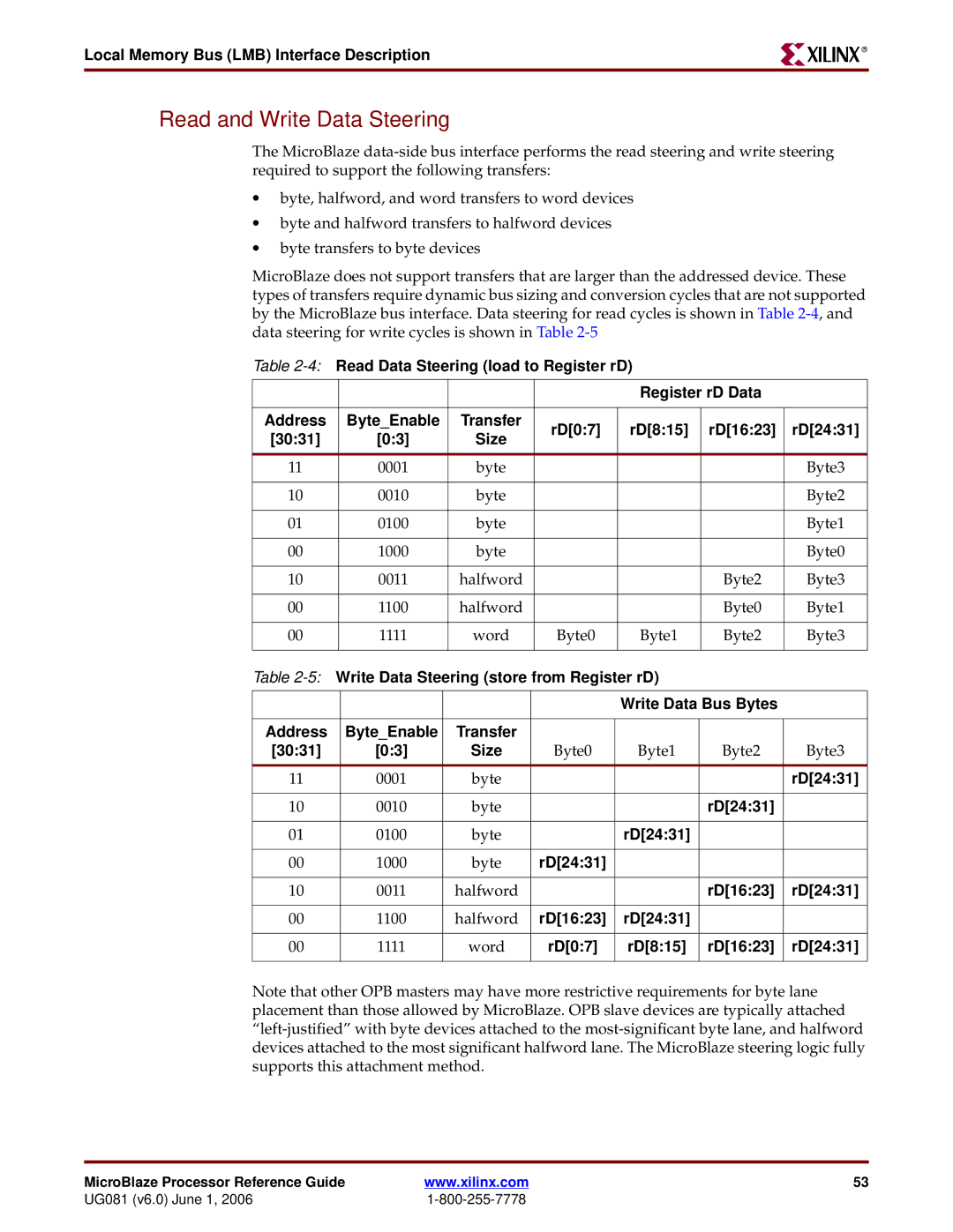
MicroBlaze does not support transfers that are larger than the addressed device. These types of transfers require dynamic bus sizing and conversion cycles that are not supported by the MicroBlaze bus interface. Data steering for read cycles is shown in Table
Table
|
|
|
| Register rD Data |
| ||
|
|
|
|
|
|
| |
Address | Byte_Enable | Transfer | rD[0:7] | rD[8:15] | rD[16:23] | rD[24:31] | |
[30:31] | [0:3] | Size | |||||
|
|
|
| ||||
|
|
|
|
|
|
| |
11 | 0001 | byte |
|
|
| Byte3 | |
|
|
|
|
|
|
| |
10 | 0010 | byte |
|
|
| Byte2 | |
|
|
|
|
|
|
| |
01 | 0100 | byte |
|
|
| Byte1 | |
|
|
|
|
|
|
| |
00 | 1000 | byte |
|
|
| Byte0 | |
|
|
|
|
|
|
| |
10 | 0011 | halfword |
|
| Byte2 | Byte3 | |
|
|
|
|
|
|
| |
00 | 1100 | halfword |
|
| Byte0 | Byte1 | |
|
|
|
|
|
|
| |
00 | 1111 | word | Byte0 | Byte1 | Byte2 | Byte3 | |
|
|
|
|
|
|
| |
Table
|
|
|
| Write Data Bus Bytes |
| |
|
|
|
|
|
|
|
Address | Byte_Enable | Transfer |
|
|
|
|
[30:31] | [0:3] | Size | Byte0 | Byte1 | Byte2 | Byte3 |
11 | 0001 | byte |
|
|
| rD[24:31] |
|
|
|
|
|
|
|
10 | 0010 | byte |
|
| rD[24:31] |
|
|
|
|
|
|
|
|
01 | 0100 | byte |
| rD[24:31] |
|
|
|
|
|
|
|
|
|
00 | 1000 | byte | rD[24:31] |
|
|
|
|
|
|
|
|
|
|
10 | 0011 | halfword |
|
| rD[16:23] | rD[24:31] |
|
|
|
|
|
|
|
00 | 1100 | halfword | rD[16:23] | rD[24:31] |
|
|
|
|
|
|
|
|
|
00 | 1111 | word | rD[0:7] | rD[8:15] | rD[16:23] | rD[24:31] |
|
|
|
|
|
|
|
Note that other OPB masters may have more restrictive requirements for byte lane placement than those allowed by MicroBlaze. OPB slave devices are typically attached
MicroBlaze Processor Reference Guide | www.xilinx.com | 53 |
UG081 (v6.0) June 1, 2006 |
|
