Modero VG-Series
AMX Limited Warranty and Disclaimer
FCC Information
Page
Table of Contents
Installation Procedures 12 and 15 Panels
Panel Calibration
Upgrading Modero Firmware 121
Displaying Stream Content 169
Troubleshooting 231 Appendix 235
Modero Multimedia Touch Panels VG-Series with Video Kits
Multimedia Streaming Video Touch Panels VG-Series
Modero Multimedia Touch Panels VG-Series with RGB Kits
Product Specifications NXD-1200VG and NXT-1200VG
1200VG Panel Specifications
Viewing Angles
Features
Panel LCD Parameters
Active Screen Area
Rear Panel Components
Front Panel Components
Environment
Included Accessories
Cont
Operating / Storage
FG2255-11
Other AMX Equipment
FG031-50
1500VG Panel Specifications
Product Specifications NXD-1500VG and NXT-1500VG
NXT models only
NXA-AVB/ETHERNET Breakout Box
Included within the Video Kit FG xxxx-xV is the following
Included within the RGB Kit FG xxxx-xxRGB is the following
FG032-50
1700VG Panel Specifications
Product Specifications NXD-1700VG and NXT-1700VG
Features
NXA-AVB/ETHERNET Breakout Box
Cont
FG033-50
Connecting and Using USB Input Devices
VG-Series Modero Connectors
Cleaning the Touch Overlay
NXA-AVB/RGB Breakout Box FG2254-11
Overview
NXA-AVB/RGB Specifications
Product Specifications
RGB RJ-45 Connector Pinouts and Signals
RGB RJ-45 connection and wiring information
Pin Signal Function
Using the HD-15 high-density connector
Installing the NXA-AVB/RGB
HD-15 Connector Pinouts
VDC power Supply
Wiring the NXA-AVB/RGB connectors and cables
PWR
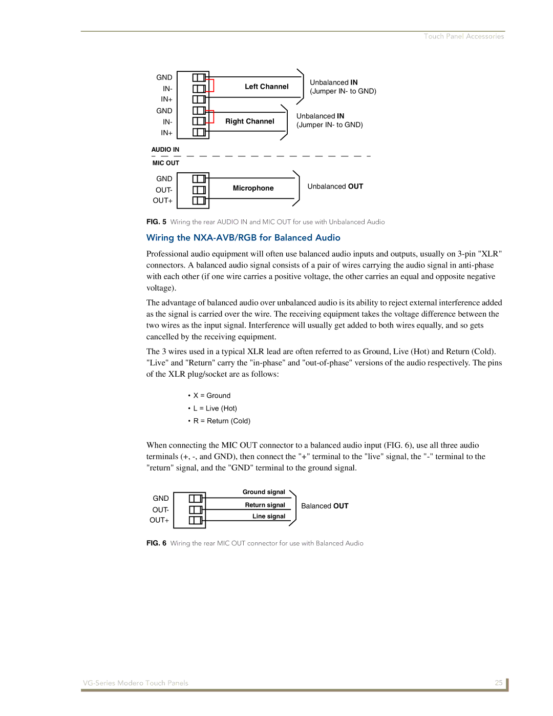
Wiring the NXA-AVB/RGB for Unbalanced Audio
USB
Wiring the NXA-AVB/RGB for Balanced Audio
Touch Panel Accessories
N E L
Wiring for Pass-Thru Computer Control
NXA-MTC/RGB Combo Table Top Cable CA2250-70
NXA-MTC/RGB Specifications
Connectors
Associated Touch Panels where used
Wiring and Connection Information
Wire Connector
Installing CAT5 Suppression Ferrites
Wire Table
NXA-RGB RGB/VGA Interface Card FG2260
Ferrite connector location on Audio/Video RJ-45 cable
Power
NXA-RGB Specifications
Resolutions Refresh Rates Descriptions
Supported Component/VGA Video Resolutions and Formats
NXA-RGB Supported Resolutions and Formats
NXA-CFTP Compact Flash FG2116-22
Optional Compact Flash Memory Upgrades
Antenna Type
NXA-PCI80211G Wireless Card FG2255-04
NXA-PCI80211G Specifications
Description
Network Architecture
Media Access Technique
Frequency Range
Modulation
Security
Installation and Upgrade of the Internal NXT Components
Remove the existing NXT Outer Housing
Location of the NXA-PCI80211G wireless card on the NXT board
Install the 802.11g mini-PCI Wireless Card
Installation of the mini-PCI card connector on main board
Install the NXA-RGB Card Component NXT
Location of the NXA-RGB card and I/O plate
Install the Compact Flash Memory Card upgrade
Close and Resecure the NXT Panel Enclosure
Removing/installing a Compact Flash Memory card
Do not Remove
Installation and Upgrade of the Internal NXD Components
Remove the existing NXD Outer Housing
Close and Resecure the NXD Panel Enclosure
Install the new 802.11g mini-PCI Wireless card NXD
Install the new RGB Card Component NXD
Install the new Compact Flash Memory card NXD
Power Voltage
NXT-BP Power Pack FG2255-10
NXT-BP Specifications
NXA-BASE/B Specifications
NXA-BASE/B Battery Base Kit FG2255K
Installing the NXA-BASE/B to an NXT Modero Panel
Checking the NXT-BP battery charge
Top view
Installing an NXT-BP into the NXA-BASE/B
Front
Charging the NXT-BP batteries with the NXA-BASE/B
NXT-BP and NXT-CHG Specifications
NXT-CHG Battery Charger Kit FG2255-50K
Green Solid
Powering the NXT-CHG
Reading NXT-CHG LED Indicator
Charging the NXT-BP batteries using the NXT-CHG
Recalibrating the batteries
Touch Panel Accessories
Upgrading to the MB-TP12/MB-TP15 Vesa Mounting Kit
Installing Internal Components
Unpacking the Panel
Removing the Original Modero Back Box
Installing the MP-TP12/15 Back Box
Finalizing the installation
Cable Installation for the MP-TP12/15 Back Box
8020MM 5264MM 5590MM 6166MM
MB-TP15 Mounting contact surface area
Clip Facing UP
Installer Leave a GAP Between the Stud and Conduit BOX to
Pre-wall Installation of the Conduit Boxes
Installing the NXD panel within a Conduit Box
Installation of the NXD Touch Panel
Installing the NXD into drywall using Expansion Clips
Cutout Front Bezel
Symmetrical
Installing the NXD into a Flat Surface using #4 screws
Installation Procedures 12 and 15 Panels
Cutout Front Bezel
Screws not included
Rack mount
Wiring a power connection
Wiring Guidelines for the 1200VG and 1500VG Panels
Preparing captive wires
Audio/Video RJ-45 Pinout Information
Audio/Video Port Connections and Wiring
Ethernet/RJ-45 Port Connections and Wiring
Pin Wire Color Function Polarity
Pin Signals Connections Pairing Color
Ethernet RJ-45 Pinouts and Signals
Upgrading the Back Box with the MB-TP17 Vesa Housing
Installing the Internal Components
Installing the MP-TP17 Back Box
62-0033-50
Cable Installation for the MP-TP17 Back Box
8321MM 8397MM 06103MM
Pre-wall Installation of the CB-TP17 Conduit Box
Before
Installing the NXD-1700VG within a CB-TP17 Conduit Box
Installation of an NXD-1700VG
Installation Procedures 17 Panels
Installing the NXD-1700VG into drywall using Expansion Clips
Connectors Left Side
Four notches are
Replacement drywall clip sets must be ordered from AMX
Installation Procedures 17 Panels
Stud beams may be 13.554
Installation Procedures 17 Panels
Installing an NXD into an optional Rack Mount Kit NXA-RK17
Wiring Guidelines for the 1700VG Panels
Lights when receiving or Transmitting Ethernet Data packets
Ethernet RJ-45 Pinouts and Signals
Installation Procedures 17 Panels
Calibrating the Modero Panel
Panel Calibration
Touch Panel Calibration Screens
Testing your Calibration
Modero Setup and System Connection
Configuring Communication
Modero connection information
Setting up the USB Driver on the PC
Configuring and Using USB with a Virtual Master
System Settings page using a USB Connection Type
Confirming the Installation of the USB Driver on the PC
Navigate back to the System Settings
Device Manager dialog showing USB device
Confirm and View the current AMX USB device connections
Assigning Communication Settings for a Virtual Master
100
Hot Swapping
Wireless Settings Page Wireless Access Overview
IP Routing
Wireless communication using a Dhcp Address
Configuring a Wireless Connection
Configuring the Panel’s Wireless IP Settings
Wireless communication using a Static IP Address
An NXA-WAP200G and the target WAP
Configuring the Card’s Wireless Security Settings
VG-Series Modero Touch Panels 105
106
These WEP Key identifier values must match for both devices
108
Configuring the Panel’s Wired IP Settings
Configuring a Wired Ethernet Connection
Choosing a Master Connection Mode Setting
Configuring the Ethernet Connection Type
Master Connection Virtual Master communication over Ethernet
These must match
114
Resides on the same Subnet as itself
G4 Web Control
Using G4 Web Control to Interact with a G4 Panel
VG-Series Modero Touch Panels 117
Using your NetLinx Master to control the G4 panels
VG-Series Modero Touch Panels 119
120
Upgrading the Modero Firmware via the USB port
Configure the panel for a USB Connection Type
Prepare NetLinx Studio for communication via the USB port
Default Modero panel value is
Confirm and Upgrade the firmware via the USB port
124
Prepare the Master for communication via an IP
Upgrading the Modero Firmware via an IP Address
Prepare the panel for communication via an IP
NetLinx Workspace window showing connected Modero panel
Verify and Upgrade the panel firmware via an IP
Upgrading Accessory Devices via an IP Address
Prepare the NXA-BASE/B for firmware transfer
Battery Base
Upgrade the NXA-BASE/B firmware via an IP
VG-Series Modero Touch Panels 131
Upgrading the NXA-RGB and NXA-AVB/RGB Firmware
RGB Adjustment page showing the default values
Setup Navigation Button Elements
Setup Navigation Buttons
Setup Page Elements
Setup
Inactivity Page Flip
Display/Panel Timeout
Timeout
Connection Status
Project Information Page Elements
Project Information
Panel Information Page Elements
Panel Information
Time & Date Setup Page Elements
Time & Date Setup
Date Display fields
Volume
Volume Page Elements
Time Display fields
Supported WAV Sampling Rates
Protected Setup
Supported sampling rates for WAV
Settings
Video Adjustment Slide-Out Option Bar
Video Adjustment Video Adjustment
Video Adjustment Page Elements
RGB Adjustment Page Elements
Video Adjustment RGB Adjustment
BOB Version
RGB Input Resolution
Phase
Version
All Contrast
All Brightness
Parameter fields
Adjusting the Incoming Signal on the RGB Adjustment
Full Screen Edit Mode
Skew
146
Good RGB signal overlap
Streaming Video Adjustment Page Elements
Video Adjustment Streaming Adjustment
Short for enCOder
Video
Codec, Sampling Rate, and Audio Channels
Audio
Charge Status
Battery Base
Battery Base Page Elements
Low Battery Warning
Limit
Base reach a point where they need to be recalibrated
Battery Status fields
Protected Setup Navigation Button Elements
Protected Setup Navigation Buttons
Device Number
Protected Setup
Protected Setup Page Elements
Reboot Panel
Keyboard Layout
Pages
G4 Web Control Page Elements
G4 Web Control
G4 Web Control Timeout
G4 Web Control Settings
Light Level field
Sensor Setup
Sensor Setup Page Elements
Light Sensor
Wake Panel On Motion
Using the Automated Brightness Control feature DIM Mode
Dim Mode Minimum
Motion Sensor
Password Setup
Password Setup
Change
Password Setup Page Elements
Panel Password
Calibration
IP Settings
Wireless Settings
Wireless Settings Page Elements
Address
Access Point MAC
164
Data Rate
System Settings Page Elements
System Settings
ICSNet is not a supported option on this panel
Firmware Pages and Descriptions 168
Displaying Stream Content
Requirements for Receiving Streamed Content
Obtaining the IP Address of the target panel
Setting up a Modero Panel to Receive and Display a Stream
Stream Profiles
Configuring the MAX-CSE for communication
These port values must use even numbers
V Setup
Configuring the MAX-CSE audio/video inputs
Sample VG-Series TPD4 panel project
Setup a streaming page within TPDesign4
Our example uses udp//192.199.99.995000
Establishing the final connection between the two units
Rtpmpeg#//IP Address of MAX-CSETarget Video Port
178
@APG
Commands
Commands
Button Assignments
@PHP
@DPG
@PDR
@PHE
Commands
@PPX
@PPM
@PPN
@PPT
@PST
@PSE
@PSP
Ppon
Ppof
Ppog
Index No Name Red Green Blue
Programming Numbers
RGB triplets and names for basic 88 colors
RGB Values for all 88 Basic Colors
186
Font ID # Font type Size
Default Font Styles and ID Numbers
Font styles and ID numbers
Border styles
Border styles
TPD4 Border Styles by Name
VG-Series Modero Touch Panels 189
APF
Button Commands
Button Commands
ANI
BCB
BAT
BAU
BCT
BCF
BFB
BDO
BLN
BIM
Entry is required
BMC
Sendcommand Panel,BMC-150,1,1,315,1,%BR%FT%TX%BM%IC%CF%CT
BMF-vt addr range,button states range,data
BMF
Cont
BNC
BMI
BML
BMP
BOP
BNN
BNT
BOS
BOR
BSM
BPP
BRD
BSF
BVP
BSO
BVL
BVN
ENA
BWW
CPF
DPF
GIV
FON
GDI
GRU
GLH
GLL
GRD
ICO
Sendcommand Panel,ICO-500.504&510.515,1&2,1
GSN
GSN-vt addr range,bargraph slider name
JSI
JSB
MDC
JST
MBT
Pass data
TXT
TEC
TEF
Effect names
UNI-vt addr range,button states range,unicode text
Sendcommand Panel,UNI-500,1,0041
Sendcommand TP,UNI-1,0,0041
UNI
Text Effects
Text Effect Names
Defineevent
Button Query Commands
?BCB
Button Query Commands
Custom Event Fields
Field Description
?BCT
?BCF
?BOP
?BMP
?BWW
?BRD
?ICO
?FON
?JSI
?JSB
?TEC
?JST
?TEF-vt addr range,button states range
Send Command Panel,?TEF-529,1
Send Command Panel,?TXT-529,1
?TEF
Panel Runtime Operations
Panel Runtime Operation Commands
Brit
@AKP
@AKR
Beep
@PKP
Setup
@EKP
Pkeyp
Tpageoff
@SOU
@TKP
Tpageon
KPS
Input Commands
Input Commands
CAL
VKS
SLT
Decimal numbers Hexidecimal values Virtual keystroke
Embedded Codes
Embedded Codes
Panel Setup Commands
Panel Setup Commands
Dynamic Image Commands
Dynamic Image Commands
RAF-resource name,data
Troubleshooting Information
Life indicator
Symptom Solution Updated my panel firmware but
My Battery Base page doesn’t
My NXT-BP battery pack is
NXA-BASE/B connected to a
Symptom Solution
Power supply
My batteries from within an
Touch panel
Symptom Solution After downloading a panel file or
Battery Base button doesn’t
Behaves strangely
Example
Text Formatting Codes for Bargraphs/Joysticks
Bargraph Text Code Inputs
Formatting Code Operations
Character Masking Rule
Text Area Input Masking
Input mask character types
Character Types
Input mask literals
Input mask ranges
Input mask next field characters
Input mask operations
Common Name Input Mask
Input mask output examples
Output Examples
Sequence Panel Information
URL Resources
Special escape sequences
Escape Sequences
Appendix 240
Appendix Modero Widescreen Touch Panels 241
It’s Your World Take Control