Manuals
/
Bosch Appliances
/
Household Appliance
/
Home Security System
Bosch Appliances
ICP-CC404
manual
Installation Guide
Models:
ICP-CC404
1
1
98
98
Download
98 pages
40.39 Kb
1
2
3
4
5
6
7
8
Specs
Install
Diagrams
Codepad Duress Alarm
Zone Defaults
Delay-1 Zone
Codepad Indicators
Fire Alarm Resetting
Access Code
Command 965 Defaults
Page 1
Image 1
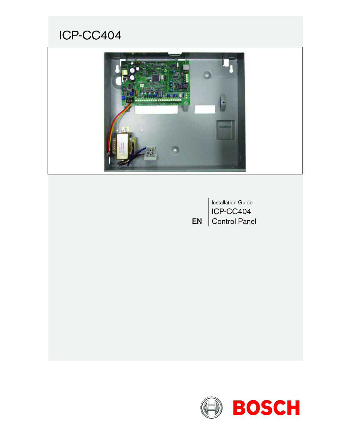
ICP-CC404
EN
Installation Guide
ICP-CC404
Control Panel
Page 1
Page 2
Page 1
Image 1
Page 1
Page 2
Contents
ICP-CC404
Installation Guide
Copyright Notice
ICP-CC404 Installation Guide Copyright Notice
Contents
ICP-CC404 Installation Guide Contents
Figures
Tables
ICP-CC404 Installation Guide 1.0 Introduction
Features
Introduction
Quick Start
Zone Defaults
Setting the Date and Time
Example
Zone Types
Codepad Indicators
ICP-CC404 Installation Guide 2.0 Programming
Programming
Programming with the Remote Codepad
Installer’s Programming Mode Commands
Installer’s Programming Commands
Programming with the Programming Key
Programming Option Bits
Command 959 Test the Programming Key
Command 958 Enable/Disable Zone Status Mode
Command 963 Copy the Programming Key to the Control Panel
Command 960 Exit from the Installers Programming Mode
Command 965 Set Up Domestic Dialing Format
Command 964 Erase the Programming Key
Command 966 Enable or Disable Auto Step Mode
Example Auto Step Mode Enabled
Command 965 Defaults
Example Auto Step Mode Disabled
Programming
Using this feature is not recommended
Disable Factory Defaults
ICP-CC404 Installation Guide 3.0 Codepad Indicators
Codepad Indicators
ICP-CP508W Eight Zone LED Codepad
ICP-CP508LW Eight Zone LCD Codepad
Audible Indicators
System Disarmed
Arming the System in Away Mode
Disarming the System from Away Mode
ICP-CC404 Installation Guide 4.0 System Operations
System Operations
Disarming the System from Stay Mode
Arming the System in Stay Mode
Entry Guard Timer for Stay Mode
Arming the System in Stay Mode
Codepad Panic Alarm
Codepad Duress Alarm
Codepad Fire Alarm
Codepad Medical Alarm
Fault Descriptions
Fault Analysis Mode
Fault Indicators
Low Battery
Date and Time
Telephone Line Fault
Sensor Watch
Horn Speaker Monitor
Indications from Remote Radio Transmitter Operations
Remote Radio Transmitter Operations
Remote Radio User Code Priority Levels
Changing or Deleting Remote Radio User Codes
Arming in Away Mode
Codepad Indicators for Remote Radio User Numbers
Disarming from Away Mode
Arming in Stay Mode
Panic Alarm
Disarming from Stay Mode
Four-Channel Remote Radio Hand- Held Transmitter Operations
ICP-CC404 Installation Guide 6.0 System Functions
Installer Code Functions
System Functions
Changing Domestic Phone Numbers
Codepad Indicators When Changing Phone Numbers
Domestic Dialing Digits
Change Telco Arming or Disarming Sequence
Telco Arming or Disarming Dialing Digits
Codepad Indicators When Changing
Telco Arming or Disarming
Sequence
Satellite Siren Service Mode
Setting Stay Mode 2 Zones
Telephone Monitor Mode Indications
Turning Telephone Monitor Mode On and Off
Event Memory Recall Mode
Master Code Functions
Master Code Functions
Remote Radio Numbers Displayed by the Codepad Indicators
Changing and Deleting User Codes
Changing and Deleting Remote Radio User Codes
Codepad Indicators When Changing Domestic Telephone Numbers
Change Telco Arming or Disarming Sequence
Setting Stay Mode 2 Zones
Turning Outputs On/Off
Hold-Down Functions
Remote Arming by Telephone
ICP-CC404 Installation Guide 7.0 Remote Arming by Telephone
ICP-CC404 Installation Guide 8.0 Alarm Link Software
Alarm Link Software
Remote Connect
ICP-CC404 Installation Guide 9.0 Domestic Dialing
Alarm Link Options
Domestic Dialing
Domestic Dialing Function
Setting Up and Programming Domestic Reporting
Dialer Reporting Formats
ICP-CC404 Installation Guide 10.0 Dialer Reporting Formats
Transmission Formats
Contact ID Format
10.1.3 4 + 2 Express Reporting Format
Point ID Codes
Example Reporting in 4 + 2 Express Format
+ 2 Express Reporting Format
Basic Pager Reporting Format
+2 Express Transmission Code Descriptions
Subscriber ID Number
Basic Pager Display Information
Zone Status
Zone Status Display Descriptions
Dialer Information
ICP-CC404 Installation Guide 11.0 Dialer Information
Primary Telephone Number for Receiver 1 and Receiver
System Status
Handshake Tone for Receiver 1 and Receiver
Secondary Telephone Number for Receiver 1 and Receiver
Transmission Format for Receiver 1 and Receiver
Subscriber ID Number for Receiver 1 and Receiver
Telco Arming Sequence
Dialing Format
Telco Disarming Sequence
Call Back Telephone Number
Telephone Line Fault Options
Ring Count
Answering Machine Bypass
Dialer Options
ICP-CC404 Installation Guide 12.0 Dialer Options
Dialer Options
Installer Code
Access Code
ICP-CC404 Installation Guide 13.0 Access Code
User Codes
User Code Priority
ICP-CC404 Installation Guide 14.0 Zone Information
Day Alarm Information
Zone Information
EOL Resistor Value
Zone Operating Information
Zone Programming
Zone Options
Zone Reporting Information
Delay-1 Zone
Zone Programming Defaults
Delay-2 Zone
Zone Types Instant Zone
Hour Holdup Zone
Keyswitch Zone
Hour Tamper Zone
12 24-Hour Burglary Zone
Silent Alarm
Delay Alarm Reporting
Keyswitch Zone Options
Latching Arm and Disarm in Away Mode
Latching Arm and Disarm in Stay Mode
Latching Disarm from Away Mode, Stay Mode 1, or Stay Mode
Latching Arm in Stay Mode
Latching Disarm from Stay Mode 1 or Stay Mode
Swinger Shutdown Count for Dialer
Swinger Shutdown Count for Siren
System Reporting Information
Zone Status Alarm Restore Code
Zone Status Bypass Reports
Zone Status Trouble Reports
Open/Close Reports
Zone Status Reporting Options
Open/Close Reporting Options
Codepad Duress Report
System Status AUX Power Supply Fail Restore Report
System Status AUX Power Supply Fail Report
System Status AC Fail Restore Report
System Status Low Battery Report
System Status Access Denied
System Status Low Battery Restore Report
System Status Reporting Options
Test Reporting Time
Programmable Outputs
ICP-CC404 Installation Guide 16.0 Programmable Outputs
Test Reporting Dialer Options
Redirecting Outputs to the Codepad Buzzer
Output Event Types
AUX Power Supply Fail
Day Alarm Enabled
Sensor Watch Alarm
Codepad Medical Alarm
Alarm When in Stay Mode
Codepad Tamper Access Denied
Alarm When in Away Mode
Mimic System Fault
Output Polarity
Normally Open, One-Shot Low with Alarm
Normally Open, One-Shot Low with Reset
Normally Low, One-Shot Open with Reset
Event Type Polarities
System Event Timers
Delay Alarm Reporting Time
Entry Guard Timer for Stay Mode
Exit Time
Sensor Watch Time
Auto Arming Time
Auto Arming Pre-Alert Timer
Auto Disarming Time
Kiss-Off Wait Time
System Options
System and Consumer Options
Sequential Handover Delay
Silent Access Denied Code Retries
Panel Powers Up Disarmed
Arm/Disarm Tracking on Power Up
Consumer Options
Optional Equipment
19.7 CP5 Eight Zone LCD Codepad CP508LW
19.9 PS101 Power Supply Module
19.8 CP105A Night Arm Station
19.10 TF008 Plug Pack TF008
Terminal Descriptions
Terminals and Descriptions
Glossary Of Terms
That an alarm was sent out
Domestic alarm reports
Stay Mode
This mode. Only the installer can program these zones
ICP-CC404 Wiring Diagram
Diagrams
ICP-CC404 Component Overlay
4 not connected
Warranty Statement
Specifications
Advice to Users
ICP-CC404 Installation Guide 21.0 Specifications
Programming Sheets
ICP-CC404 Installation Guide 22.0 Programming Sheets
22.0 Programming Sheets
Burglary zones and four 24-hr zones
Programming Sheets
22.0
ICP-CC404 Installation Guide 22.0 Programming Sheets
374 to 392 to Strobe Output
ICP-CC404 Installation Guide 22.0 Programming Sheets
22.0 Programming Sheets
PRC
Country Codes
ICP-CC404 Installation Guide Contents
Index
ICP-CC404 Installation Guide Index
Hold Down Function
Pulse Count
Bosch Security Systems, Inc. F01U089401-02
Top
Page
Image
Contents