100


90


80


70


Limit

60


mA For 0% Demand Limit,


DMZE


Demand

50


40


%


30


20


mA For 100% Demand Limit,


DMMX


10


0


0

2

4

6

8

10

12

14

16

18

20


mA Demand Limit Signal


a30-4831

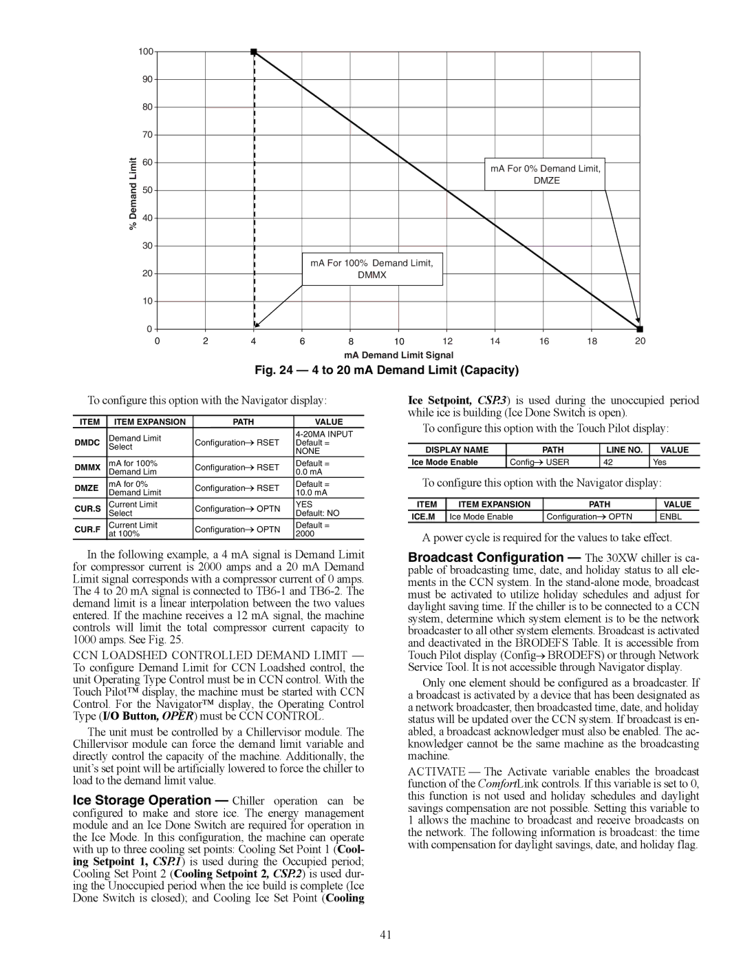
Fig. 24 — 4 to 20 mA Demand Limit (Capacity)

To configure this option with the Navigator display:

ITEM

ITEM EXPANSION

PATH

VALUE

DMDC

Demand Limit

ConfigurationRSET

4-20MA INPUT

Default =


Select


NONE


DMMX

mA for 100%

ConfigurationRSET

Default =


Demand Lim


0.0 mA

DMZE

mA for 0%

ConfigurationRSET

Default =

Demand Limit

10.0 mA


CUR.S

Current Limit

ConfigurationOPTN

YES


Select


Default: NO

CUR.F

Current Limit

ConfigurationOPTN

Default =


at 100%


2000

In the following example, a 4 mA signal is Demand Limit for compressor current is 2000 amps and a 20 mA Demand Limit signal corresponds with a compressor current of 0 amps. The 4 to 20 mA signal is connected to TB6-1 and TB6-2. The demand limit is a linear interpolation between the two values entered. If the machine receives a 12 mA signal, the machine controls will limit the total compressor current capacity to 1000 amps. See Fig. 25.

CCN LOADSHED CONTROLLED DEMAND LIMIT — To configure Demand Limit for CCN Loadshed control, the unit Operating Type Control must be in CCN control. With the Touch Pilot™ display, the machine must be started with CCN Control. For the Navigator™ display, the Operating Control Type (I/O Button, OPER) must be CCN CONTROL.

The unit must be controlled by a Chillervisor module. The Chillervisor module can force the demand limit variable and directly control the capacity of the machine. Additionally, the unit’s set point will be artificially lowered to force the chiller to load to the demand limit value.

Ice Storage Operation — Chiller operation can be configured to make and store ice. The energy management module and an Ice Done Switch are required for operation in the Ice Mode. In this configuration, the machine can operate with up to three cooling set points: Cooling Set Point 1 (Cool- ing Setpoint 1, CSP.1) is used during the Occupied period; Cooling Set Point 2 (Cooling Setpoint 2, CSP.2) is used dur- ing the Unoccupied period when the ice build is complete (Ice Done Switch is closed); and Cooling Ice Set Point (Cooling

Ice Setpoint, CSP.3) is used during the unoccupied period while ice is building (Ice Done Switch is open).

To configure this option with the Touch Pilot display:

DISPLAY NAME

PATH

LINE NO.

VALUE

Ice Mode Enable

ConfigUSER

42

Yes

To configure this option with the Navigator display:

ITEM

ITEM EXPANSION

PATH

VALUE

ICE.M

Ice Mode Enable

ConfigurationOPTN

ENBL

A power cycle is required for the values to take effect.

Broadcast Configuration — The 30XW chiller is ca- pable of broadcasting time, date, and holiday status to all ele- ments in the CCN system. In the stand-alone mode, broadcast must be activated to utilize holiday schedules and adjust for daylight saving time. If the chiller is to be connected to a CCN system, determine which system element is to be the network broadcaster to all other system elements. Broadcast is activated and deactivated in the BRODEFS Table. It is accessible from Touch Pilot display (ConfigBRODEFS) or through Network Service Tool. It is not accessible through Navigator display.

Only one element should be configured as a broadcaster. If a broadcast is activated by a device that has been designated as a network broadcaster, then broadcasted time, date, and holiday status will be updated over the CCN system. If broadcast is en- abled, a broadcast acknowledger must also be enabled. The ac- knowledger cannot be the same machine as the broadcasting machine.

ACTIVATE — The Activate variable enables the broadcast function of the ComfortLink controls. If this variable is set to 0, this function is not used and holiday schedules and daylight savings compensation are not possible. Setting this variable to 1 allows the machine to broadcast and receive broadcasts on the network. The following information is broadcast: the time with compensation for daylight savings, date, and holiday flag.

41

Page 41
Image 41
Carrier 30XW150-400 Power cycle is required for the values to take effect, Dmmx, Item Expansion Path Value ICE.M, Enbl

30XW150-400 specifications

The Carrier 30XW150-400 series is a line of water-cooled chillers that exemplifies innovation, efficiency, and reliability in commercial cooling solutions. Designed for medium to large-scale applications, this series is ideal for a variety of settings, including commercial buildings, industrial processes, and chilled water systems.

One of the standout features of the Carrier 30XW series is its efficiency. The chillers utilize advanced variable-speed compressor technology, which allows the units to adapt to varying cooling loads while minimizing energy consumption. This technology not only reduces operational costs but also contributes to better environmental sustainability by lowering greenhouse gas emissions.

The 30XW series chillers are equipped with high-efficiency, scroll compressors that operate quietly and provide significant energy savings. By utilizing enhanced economizer controls, these units can achieve higher efficiency ratings, especially in part-load conditions. The result is an impressive Energy Efficiency Ratio (EER) and Seasonal Energy Efficiency Ratio (SEER), making these units a smart choice for energy-conscious businesses.

In terms of reliability, the Carrier 30XW150-400 series features robust construction and an array of safety and monitoring systems. The units come with advanced diagnostics that help in quickly identifying and addressing any operational issues. This proactive approach ensures reliability and minimizes downtime, which is crucial for maintaining optimal temperature controls in critical environments.

Additionally, the chillers incorporate environmentally friendly refrigerants that comply with the latest regulations, making them a sustainable choice for modern commercial applications. Their compact design allows for flexible installation options, and the integrated control systems provide the ability to optimize performance based on specific building management demands.

User-friendly interfaces and remote monitoring capabilities further enhance the ease of operation, allowing facility managers to have real-time insight into performance metrics and system health. This level of control contributes to better maintenance planning and maximizes the lifespan of the equipment.

In summary, the Carrier 30XW150-400 series of water-cooled chillers combines advanced technology, energy efficiency, and reliable performance, making it an ideal solution for various commercial and industrial cooling needs. With its commitment to innovation and sustainability, Carrier continues to set the standard in the HVAC industry.