30XW150-400 specifications
The Carrier 30XW150-400 series is a line of water-cooled chillers that exemplifies innovation, efficiency, and reliability in commercial cooling solutions. Designed for medium to large-scale applications, this series is ideal for a variety of settings, including commercial buildings, industrial processes, and chilled water systems.One of the standout features of the Carrier 30XW series is its efficiency. The chillers utilize advanced variable-speed compressor technology, which allows the units to adapt to varying cooling loads while minimizing energy consumption. This technology not only reduces operational costs but also contributes to better environmental sustainability by lowering greenhouse gas emissions.
The 30XW series chillers are equipped with high-efficiency, scroll compressors that operate quietly and provide significant energy savings. By utilizing enhanced economizer controls, these units can achieve higher efficiency ratings, especially in part-load conditions. The result is an impressive Energy Efficiency Ratio (EER) and Seasonal Energy Efficiency Ratio (SEER), making these units a smart choice for energy-conscious businesses.
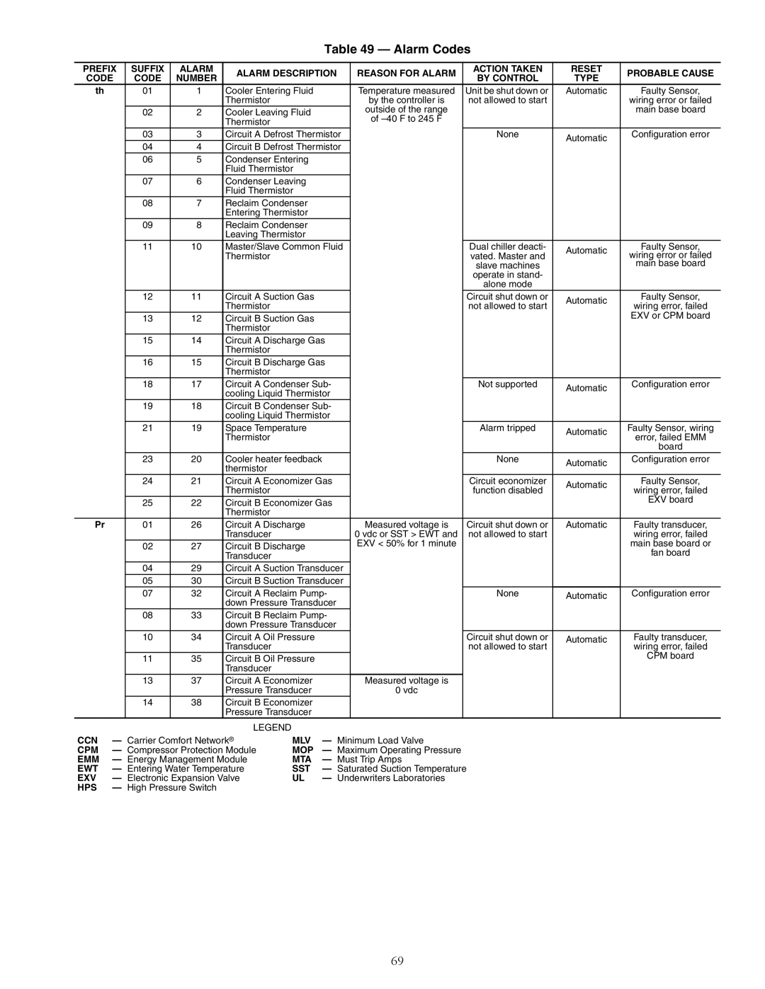
In terms of reliability, the Carrier 30XW150-400 series features robust construction and an array of safety and monitoring systems. The units come with advanced diagnostics that help in quickly identifying and addressing any operational issues. This proactive approach ensures reliability and minimizes downtime, which is crucial for maintaining optimal temperature controls in critical environments.
Additionally, the chillers incorporate environmentally friendly refrigerants that comply with the latest regulations, making them a sustainable choice for modern commercial applications. Their compact design allows for flexible installation options, and the integrated control systems provide the ability to optimize performance based on specific building management demands.
User-friendly interfaces and remote monitoring capabilities further enhance the ease of operation, allowing facility managers to have real-time insight into performance metrics and system health. This level of control contributes to better maintenance planning and maximizes the lifespan of the equipment.
In summary, the Carrier 30XW150-400 series of water-cooled chillers combines advanced technology, energy efficiency, and reliable performance, making it an ideal solution for various commercial and industrial cooling needs. With its commitment to innovation and sustainability, Carrier continues to set the standard in the HVAC industry.
