Carrier 30XW150-400 specifications Navigator Display Module

Models: 30XW150-400

1 148
Download 148 pages 52.93 Kb
Page 8
Image 8
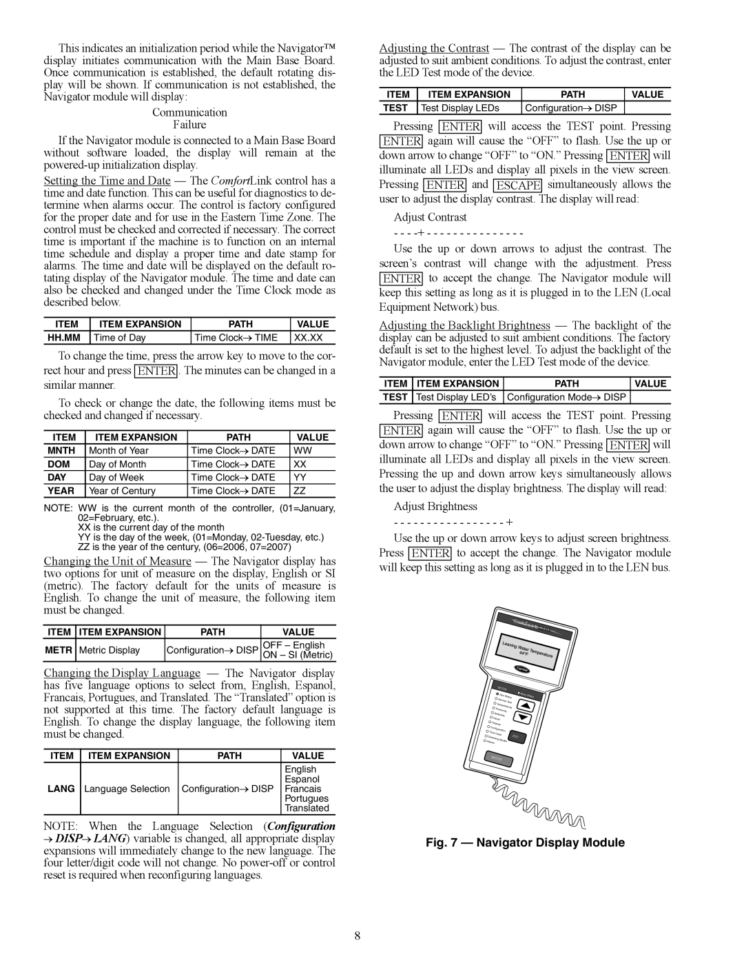
Fig. 7 — Navigator Display Module

This indicates an initialization period while the Navigator™ display initiates communication with the Main Base Board. Once communication is established, the default rotating dis- play will be shown. If communication is not established, the Navigator module will display:

Communication

Failure

If the Navigator module is connected to a Main Base Board without software loaded, the display will remain at the powered-up initialization display.

Setting the Time and Date — The ComfortLink control has a time and date function. This can be useful for diagnostics to de- termine when alarms occur. The control is factory configured for the proper date and for use in the Eastern Time Zone. The control must be checked and corrected if necessary. The correct time is important if the machine is to function on an internal time schedule and display a proper time and date stamp for alarms. The time and date will be displayed on the default ro- tating display of the Navigator module. The time and date can also be checked and changed under the Time Clock mode as described below.

ITEM

ITEM EXPANSION

PATH

VALUE

HH.MM

Time of Day

Time ClockTIME

XX.XX

To change the time, press the arrow key to move to the cor- rect hour and press ENTER . The minutes can be changed in a similar manner.

To check or change the date, the following items must be checked and changed if necessary.

ITEM

ITEM EXPANSION

PATH

VALUE

MNTH

Month of Year

Time ClockDATE

WW

DOM

Day of Month

Time ClockDATE

XX

DAY

Day of Week

Time ClockDATE

YY

YEAR

Year of Century

Time ClockDATE

ZZ

NOTE: WW is the current month of the controller, (01=January, 02=February, etc.).

XXis the current day of the month

YYis the day of the week, (01=Monday, 02-Tuesday, etc.)

ZZis the year of the century, (06=2006, 07=2007)

Changing the Unit of Measure — The Navigator display has two options for unit of measure on the display, English or SI (metric). The factory default for the units of measure is English. To change the unit of measure, the following item must be changed.

ITEM

ITEM EXPANSION

PATH

VALUE

METR

Metric Display

ConfigurationDISP

OFF – English


ON – SI (Metric)

Changing the Display Language — The Navigator display has five language options to select from, English, Espanol, Francais, Portugues, and Translated. The “Translated” option is not supported at this time. The factory default language is English. To change the display language, the following item must be changed.

ITEM

ITEM EXPANSION

PATH

VALUE


English

LANG


ConfigurationDISP

Espanol

Language Selection

Francais


Portugues


Translated

NOTE: When the Language Selection (Configuration

DISPLANG) variable is changed, all appropriate display expansions will immediately change to the new language. The four letter/digit code will not change. No power-off or control reset is required when reconfiguring languages.

Adjusting the Contrast — The contrast of the display can be adjusted to suit ambient conditions. To adjust the contrast, enter the LED Test mode of the device.

ITEM

ITEM EXPANSION

PATH

VALUE

TEST

Test Display LEDs

ConfigurationDISP


Pressing ENTER will access the TEST point. Pressing ENTER again will cause the “OFF” to flash. Use the up or down arrow to change “OFF” to “ON.” Pressing ENTER will illuminate all LEDs and display all pixels in the view screen. Pressing ENTER and ESCAPE simultaneously allows the user to adjust the display contrast. The display will read:

Adjust Contrast

- - - -+ - - - - - - - - - - - - - - -

Use the up or down arrows to adjust the contrast. The screen’s contrast will change with the adjustment. Press ENTER to accept the change. The Navigator module will keep this setting as long as it is plugged in to the LEN (Local Equipment Network) bus.

Adjusting the Backlight Brightness — The backlight of the display can be adjusted to suit ambient conditions. The factory default is set to the highest level. To adjust the backlight of the Navigator module, enter the LED Test mode of the device.

ITEM

ITEM EXPANSION

PATH

VALUE

TEST

Test Display LED’s

Configuration ModeDISP


Pressing ENTER will access the TEST point. Pressing ENTER again will cause the “OFF” to flash. Use the up or down arrow to change “OFF” to “ON.” Pressing ENTER will illuminate all LEDs and display all pixels in the view screen. Pressing the up and down arrow keys simultaneously allows the user to adjust the display brightness. The display will read:

Adjust Brightness

- - - - - - - - - - - - - - - - - +

Use the up or down arrow keys to adjust screen brightness. Press ENTER to accept the change. The Navigator module will keep this setting as long as it is plugged in to the LEN bus.

Comfort

Link


MODE


Run

Status

Alarm

Status


Service

Test


Temperatures


Pressures


Setpoints


Inputs


Outputs


Configuration


Time

Clock


ESC


Operating

Modes


Alarms


ENTER


a30-3924

Fig. 7 — Navigator Display Module

8

Page 8
Image 8
Carrier 30XW150-400 specifications Navigator Display Module