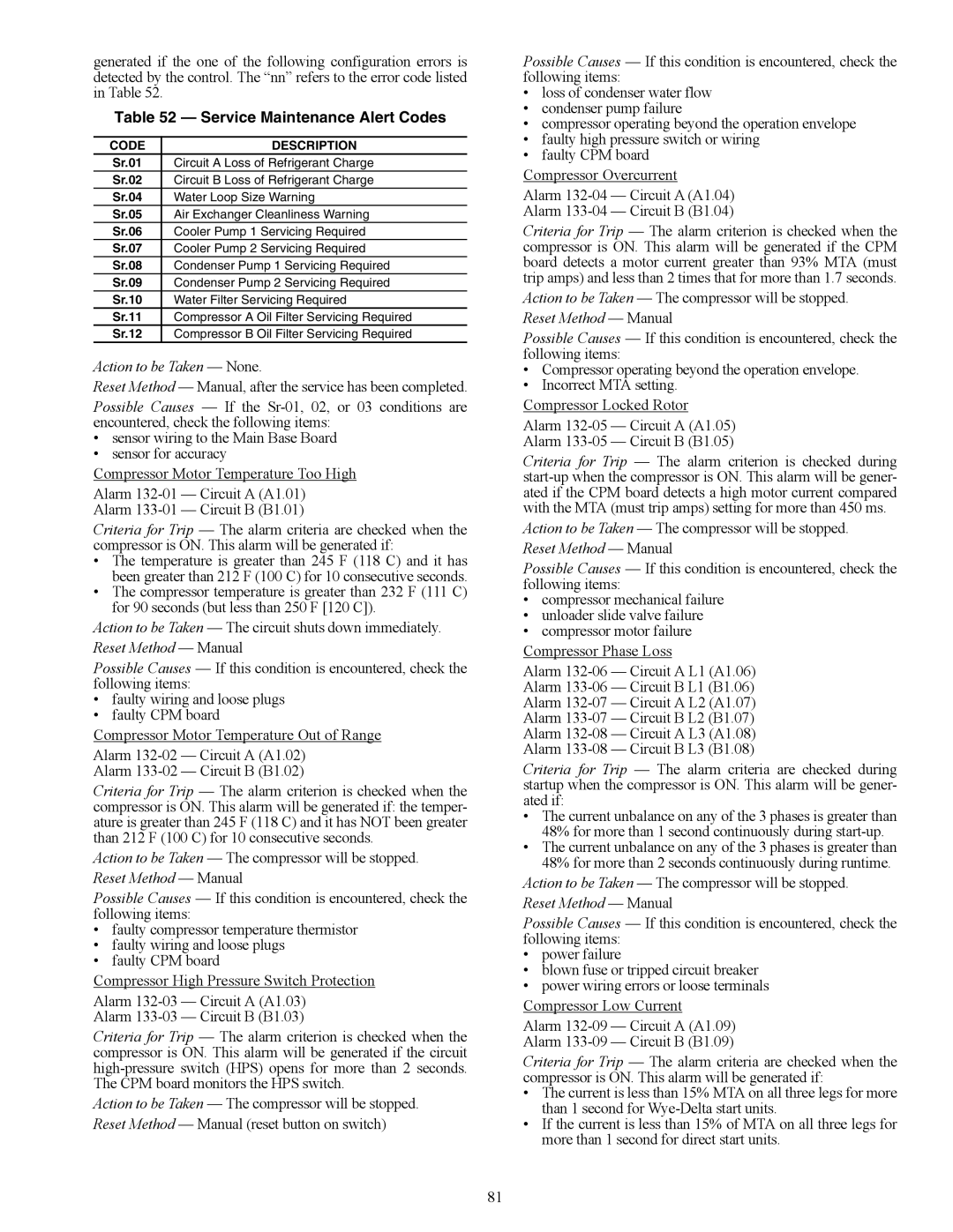
generated if the one of the following configuration errors is detected by the control. The “nn” refers to the error code listed in Table 52.

Table 52 — Service Maintenance Alert Codes

CODE

DESCRIPTION

Sr.01

Circuit A Loss of Refrigerant Charge

Sr.02

Circuit B Loss of Refrigerant Charge

Sr.04

Water Loop Size Warning

Sr.05

Air Exchanger Cleanliness Warning

Sr.06

Cooler Pump 1 Servicing Required

Sr.07

Cooler Pump 2 Servicing Required

Sr.08

Condenser Pump 1 Servicing Required

Sr.09

Condenser Pump 2 Servicing Required

Sr.10

Water Filter Servicing Required

Sr.11

Compressor A Oil Filter Servicing Required

Sr.12

Compressor B Oil Filter Servicing Required

Action to be Taken — None.

Reset Method — Manual, after the service has been completed.

Possible Causes — If the Sr-01, 02, or 03 conditions are encountered, check the following items:

sensor wiring to the Main Base Board

sensor for accuracy

Compressor Motor Temperature Too High

Alarm 132-01 — Circuit A (A1.01)

Alarm 133-01 — Circuit B (B1.01)

Criteria for Trip — The alarm criteria are checked when the compressor is ON. This alarm will be generated if:

The temperature is greater than 245 F (118 C) and it has been greater than 212 F (100 C) for 10 consecutive seconds.

The compressor temperature is greater than 232 F (111 C) for 90 seconds (but less than 250 F [120 C]).

Action to be Taken — The circuit shuts down immediately.

Reset Method — Manual

Possible Causes — If this condition is encountered, check the following items:

faulty wiring and loose plugs

faulty CPM board

Compressor Motor Temperature Out of Range

Alarm 132-02 — Circuit A (A1.02)

Alarm 133-02 — Circuit B (B1.02)

Criteria for Trip — The alarm criterion is checked when the compressor is ON. This alarm will be generated if: the temper- ature is greater than 245 F (118 C) and it has NOT been greater than 212 F (100 C) for 10 consecutive seconds.

Action to be Taken — The compressor will be stopped.

Reset Method — Manual

Possible Causes — If this condition is encountered, check the following items:

faulty compressor temperature thermistor

faulty wiring and loose plugs

faulty CPM board

Compressor High Pressure Switch Protection

Alarm 132-03 — Circuit A (A1.03)

Alarm 133-03 — Circuit B (B1.03)

Criteria for Trip — The alarm criterion is checked when the compressor is ON. This alarm will be generated if the circuit high-pressure switch (HPS) opens for more than 2 seconds. The CPM board monitors the HPS switch.

Action to be Taken — The compressor will be stopped. Reset Method — Manual (reset button on switch)

Possible Causes — If this condition is encountered, check the following items:

loss of condenser water flow

condenser pump failure

compressor operating beyond the operation envelope

faulty high pressure switch or wiring

faulty CPM board

Compressor Overcurrent

Alarm 132-04 — Circuit A (A1.04)

Alarm 133-04 — Circuit B (B1.04)

Criteria for Trip — The alarm criterion is checked when the compressor is ON. This alarm will be generated if the CPM board detects a motor current greater than 93% MTA (must trip amps) and less than 2 times that for more than 1.7 seconds. Action to be Taken — The compressor will be stopped.

Reset Method — Manual

Possible Causes — If this condition is encountered, check the following items:

Compressor operating beyond the operation envelope.

Incorrect MTA setting.

Compressor Locked Rotor

Alarm 132-05 — Circuit A (A1.05)

Alarm 133-05 — Circuit B (B1.05)

Criteria for Trip — The alarm criterion is checked during start-up when the compressor is ON. This alarm will be gener- ated if the CPM board detects a high motor current compared with the MTA (must trip amps) setting for more than 450 ms.

Action to be Taken — The compressor will be stopped.

Reset Method — Manual

Possible Causes — If this condition is encountered, check the following items:

compressor mechanical failure

unloader slide valve failure

compressor motor failure

Compressor Phase Loss

Alarm 132-06 — Circuit A L1 (A1.06)

Alarm 133-06 — Circuit B L1 (B1.06)

Alarm 132-07 — Circuit A L2 (A1.07)

Alarm 133-07 — Circuit B L2 (B1.07)

Alarm 132-08 — Circuit A L3 (A1.08)

Alarm 133-08 — Circuit B L3 (B1.08)

Criteria for Trip — The alarm criteria are checked during startup when the compressor is ON. This alarm will be gener- ated if:

The current unbalance on any of the 3 phases is greater than 48% for more than 1 second continuously during start-up.

The current unbalance on any of the 3 phases is greater than 48% for more than 2 seconds continuously during runtime.

Action to be Taken — The compressor will be stopped.

Reset Method — Manual

Possible Causes — If this condition is encountered, check the following items:

power failure

blown fuse or tripped circuit breaker

power wiring errors or loose terminals

Compressor Low Current

Alarm 132-09 — Circuit A (A1.09)

Alarm 133-09 — Circuit B (B1.09)

Criteria for Trip — The alarm criteria are checked when the compressor is ON. This alarm will be generated if:

The current is less than 15% MTA on all three legs for more than 1 second for Wye-Delta start units.

If the current is less than 15% of MTA on all three legs for more than 1 second for direct start units.

81

Page 81
Image 81
Carrier 30XW150-400 specifications Service Maintenance Alert Codes, Code Description

30XW150-400 specifications

The Carrier 30XW150-400 series is a line of water-cooled chillers that exemplifies innovation, efficiency, and reliability in commercial cooling solutions. Designed for medium to large-scale applications, this series is ideal for a variety of settings, including commercial buildings, industrial processes, and chilled water systems.

One of the standout features of the Carrier 30XW series is its efficiency. The chillers utilize advanced variable-speed compressor technology, which allows the units to adapt to varying cooling loads while minimizing energy consumption. This technology not only reduces operational costs but also contributes to better environmental sustainability by lowering greenhouse gas emissions.

The 30XW series chillers are equipped with high-efficiency, scroll compressors that operate quietly and provide significant energy savings. By utilizing enhanced economizer controls, these units can achieve higher efficiency ratings, especially in part-load conditions. The result is an impressive Energy Efficiency Ratio (EER) and Seasonal Energy Efficiency Ratio (SEER), making these units a smart choice for energy-conscious businesses.

In terms of reliability, the Carrier 30XW150-400 series features robust construction and an array of safety and monitoring systems. The units come with advanced diagnostics that help in quickly identifying and addressing any operational issues. This proactive approach ensures reliability and minimizes downtime, which is crucial for maintaining optimal temperature controls in critical environments.

Additionally, the chillers incorporate environmentally friendly refrigerants that comply with the latest regulations, making them a sustainable choice for modern commercial applications. Their compact design allows for flexible installation options, and the integrated control systems provide the ability to optimize performance based on specific building management demands.

User-friendly interfaces and remote monitoring capabilities further enhance the ease of operation, allowing facility managers to have real-time insight into performance metrics and system health. This level of control contributes to better maintenance planning and maximizes the lifespan of the equipment.

In summary, the Carrier 30XW150-400 series of water-cooled chillers combines advanced technology, energy efficiency, and reliable performance, making it an ideal solution for various commercial and industrial cooling needs. With its commitment to innovation and sustainability, Carrier continues to set the standard in the HVAC industry.