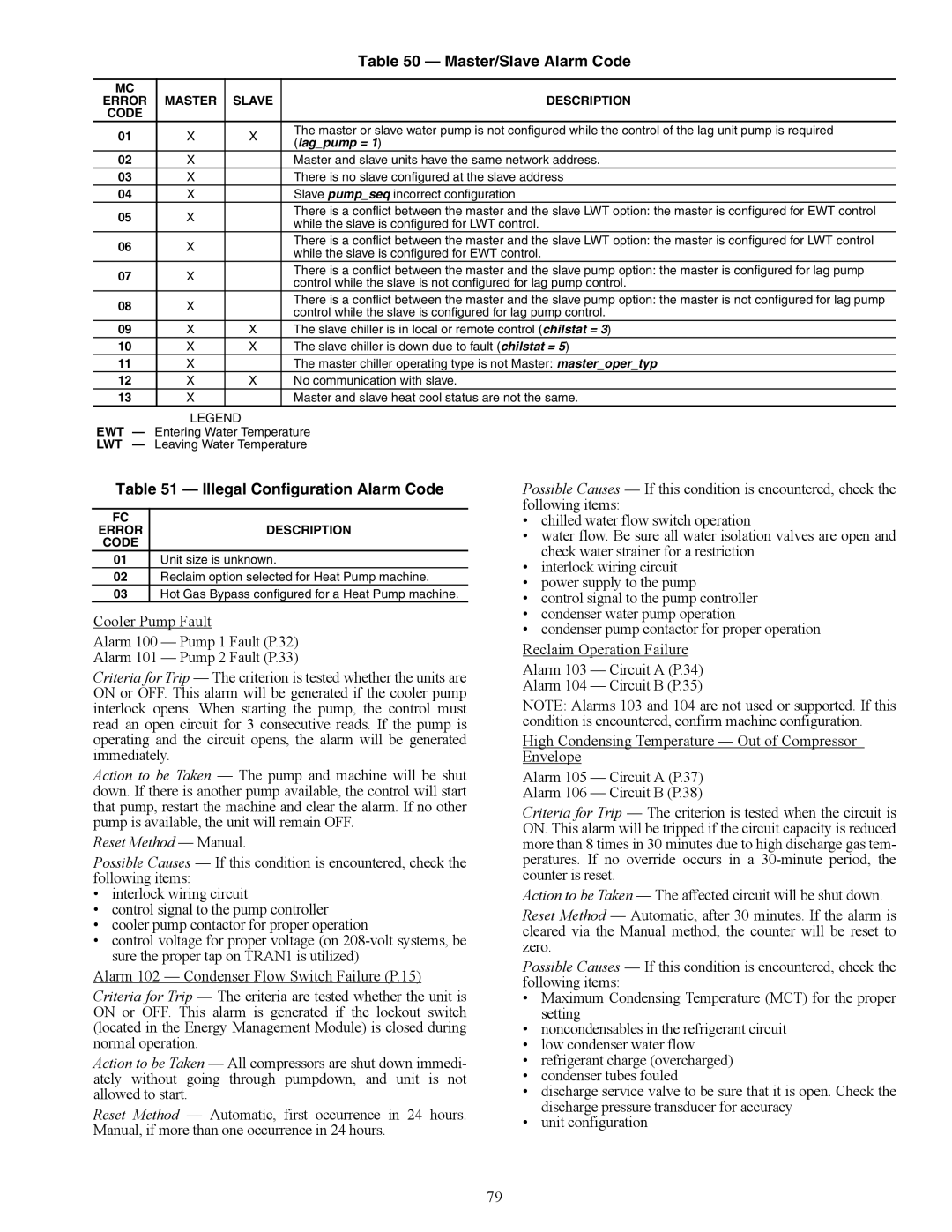
Table 50 — Master/Slave Alarm Code


MC


ERROR

MASTER

SLAVE

DESCRIPTION

CODE


01

X

X

The master or slave water pump is not configured while the control of the lag unit pump is required

(lag_pump = 1)


02

X


Master and slave units have the same network address.

03

X


There is no slave configured at the slave address

04

X


Slave pump_seq incorrect configuration

05

X


There is a conflict between the master and the slave LWT option: the master is configured for EWT control


while the slave is configured for LWT control.


06

X


There is a conflict between the master and the slave LWT option: the master is configured for LWT control


while the slave is configured for EWT control.


07

X


There is a conflict between the master and the slave pump option: the master is configured for lag pump


control while the slave is not configured for lag pump control.


08

X


There is a conflict between the master and the slave pump option: the master is not configured for lag pump


control while the slave is configured for lag pump control.


09

X

X

The slave chiller is in local or remote control (chilstat = 3)

10

X

X

The slave chiller is down due to fault (chilstat = 5)

11

X


The master chiller operating type is not Master: master_oper_typ

12

X

X

No communication with slave.

13

X


Master and slave heat cool status are not the same.

LEGEND

EWT — Entering Water Temperature

LWT — Leaving Water Temperature

Table 51 — Illegal Configuration Alarm Code

FC


ERROR

DESCRIPTION

CODE


01Unit size is unknown.

02Reclaim option selected for Heat Pump machine.

03Hot Gas Bypass configured for a Heat Pump machine.

Cooler Pump Fault

Alarm 100 — Pump 1 Fault (P.32)

Alarm 101 — Pump 2 Fault (P.33)

Criteria for Trip — The criterion is tested whether the units are ON or OFF. This alarm will be generated if the cooler pump interlock opens. When starting the pump, the control must read an open circuit for 3 consecutive reads. If the pump is operating and the circuit opens, the alarm will be generated immediately.

Action to be Taken — The pump and machine will be shut down. If there is another pump available, the control will start that pump, restart the machine and clear the alarm. If no other pump is available, the unit will remain OFF.

Reset Method — Manual.

Possible Causes — If this condition is encountered, check the following items:

interlock wiring circuit

control signal to the pump controller

cooler pump contactor for proper operation

control voltage for proper voltage (on 208-volt systems, be sure the proper tap on TRAN1 is utilized)

Alarm 102 — Condenser Flow Switch Failure (P.15)

Criteria for Trip — The criteria are tested whether the unit is ON or OFF. This alarm is generated if the lockout switch (located in the Energy Management Module) is closed during normal operation.

Action to be Taken — All compressors are shut down immedi- ately without going through pumpdown, and unit is not allowed to start.

Reset Method — Automatic, first occurrence in 24 hours. Manual, if more than one occurrence in 24 hours.

Possible Causes — If this condition is encountered, check the following items:

chilled water flow switch operation

water flow. Be sure all water isolation valves are open and check water strainer for a restriction

interlock wiring circuit

power supply to the pump

control signal to the pump controller

condenser water pump operation

condenser pump contactor for proper operation

Reclaim Operation Failure

Alarm 103 — Circuit A (P.34)

Alarm 104 — Circuit B (P.35)

NOTE: Alarms 103 and 104 are not used or supported. If this condition is encountered, confirm machine configuration.

High Condensing Temperature — Out of Compressor Envelope

Alarm 105 — Circuit A (P.37)

Alarm 106 — Circuit B (P.38)

Criteria for Trip — The criterion is tested when the circuit is ON. This alarm will be tripped if the circuit capacity is reduced more than 8 times in 30 minutes due to high discharge gas tem- peratures. If no override occurs in a 30-minute period, the counter is reset.

Action to be Taken — The affected circuit will be shut down. Reset Method — Automatic, after 30 minutes. If the alarm is cleared via the Manual method, the counter will be reset to zero.

Possible Causes — If this condition is encountered, check the following items:

Maximum Condensing Temperature (MCT) for the proper setting

noncondensables in the refrigerant circuit

low condenser water flow

refrigerant charge (overcharged)

condenser tubes fouled

discharge service valve to be sure that it is open. Check the discharge pressure transducer for accuracy

unit configuration

79

Page 79
Image 79
Carrier 30XW150-400 specifications Master/Slave Alarm Code, Illegal Configuration Alarm Code

30XW150-400 specifications

The Carrier 30XW150-400 series is a line of water-cooled chillers that exemplifies innovation, efficiency, and reliability in commercial cooling solutions. Designed for medium to large-scale applications, this series is ideal for a variety of settings, including commercial buildings, industrial processes, and chilled water systems.

One of the standout features of the Carrier 30XW series is its efficiency. The chillers utilize advanced variable-speed compressor technology, which allows the units to adapt to varying cooling loads while minimizing energy consumption. This technology not only reduces operational costs but also contributes to better environmental sustainability by lowering greenhouse gas emissions.

The 30XW series chillers are equipped with high-efficiency, scroll compressors that operate quietly and provide significant energy savings. By utilizing enhanced economizer controls, these units can achieve higher efficiency ratings, especially in part-load conditions. The result is an impressive Energy Efficiency Ratio (EER) and Seasonal Energy Efficiency Ratio (SEER), making these units a smart choice for energy-conscious businesses.

In terms of reliability, the Carrier 30XW150-400 series features robust construction and an array of safety and monitoring systems. The units come with advanced diagnostics that help in quickly identifying and addressing any operational issues. This proactive approach ensures reliability and minimizes downtime, which is crucial for maintaining optimal temperature controls in critical environments.

Additionally, the chillers incorporate environmentally friendly refrigerants that comply with the latest regulations, making them a sustainable choice for modern commercial applications. Their compact design allows for flexible installation options, and the integrated control systems provide the ability to optimize performance based on specific building management demands.

User-friendly interfaces and remote monitoring capabilities further enhance the ease of operation, allowing facility managers to have real-time insight into performance metrics and system health. This level of control contributes to better maintenance planning and maximizes the lifespan of the equipment.

In summary, the Carrier 30XW150-400 series of water-cooled chillers combines advanced technology, energy efficiency, and reliable performance, making it an ideal solution for various commercial and industrial cooling needs. With its commitment to innovation and sustainability, Carrier continues to set the standard in the HVAC industry.